Modular block switch assembly

a module block switch and switch assembly technology, applied in the field of rocker-type switches, can solve the problems of substantial change or reconfiguration of switch parts, increase certain problems of the conventional rocker-type switch that remains to be solved, so as to reduce the cost of the overall product line, eliminate tolerance error stacking, and ensure the effect of accurate fit and alignment of parts and switch contacts

Active Publication Date: 2005-05-10
EATON INTELLIGENT POWER LIMITED
View PDF23 Cites 64 Cited by
  • Summary
  • Abstract
  • Description
  • Claims
  • Application Information

AI Technical Summary

Benefits of technology

[0006]It is therefore a principal object of the present invention to provide a rocker-type switch that can be readily configured to single-pole, double-pole, 3-way, or 4-way switch arrangements with minimal change to the surrounding parts. Specifically, it is desired to provide a rocker-type switch in which a modular block subassembly is used with interchangeable switch contacts to enable reconfiguration for other switch configurations with only minimal change to the surrounding parts. It is another object of the invention to limit the manufacture of insulative parts of expensive, high temperature plastic material to a modular block subassembly that can be used for different switch configurations, thereby minimizing the costs for the overall product line. It is yet another object of the invention to eliminate tolerance error stack-up when parts are assembled together, thereby providing more accurate fit and alignment of parts and switch contacts.

Problems solved by technology

While there have been many variations of and improvements to the rocker-type switch, the conventional rocker-type switch still has certain problems that remain to be solved.
One main problem is that changing the arrangement of the rocker-type switch to single-pole, double-pole, 3-way, or 4-way switch configurations requires that different terminal plates or wiring arrangements be used with different insulative parts in the terminal housing subassembly, thereby requiring substantial change to or reconfiguration of the switch parts.
Also, the manufacture of different insulative parts of expensive, high temperature plastic material increases the costs for the overall product line.
The required assembly of different manufactured parts in different configurations also results in tolerance error stack-up when the parts are assembled together, thereby leading to problems in terms of fit and alignment of the parts and the switch contacts.

Method used


Image

  • Modular block switch assembly
  • Modular block switch assembly
  • Modular block switch assembly

Examples


Embodiment Construction

[0030]Certain preferred embodiments of the improved rocker-type switch of the present invention are described in detail below. It is understood that many other variations and modifications could be implemented by those skilled in the field to which this invention pertains, given the principles of the invention disclosed herein.

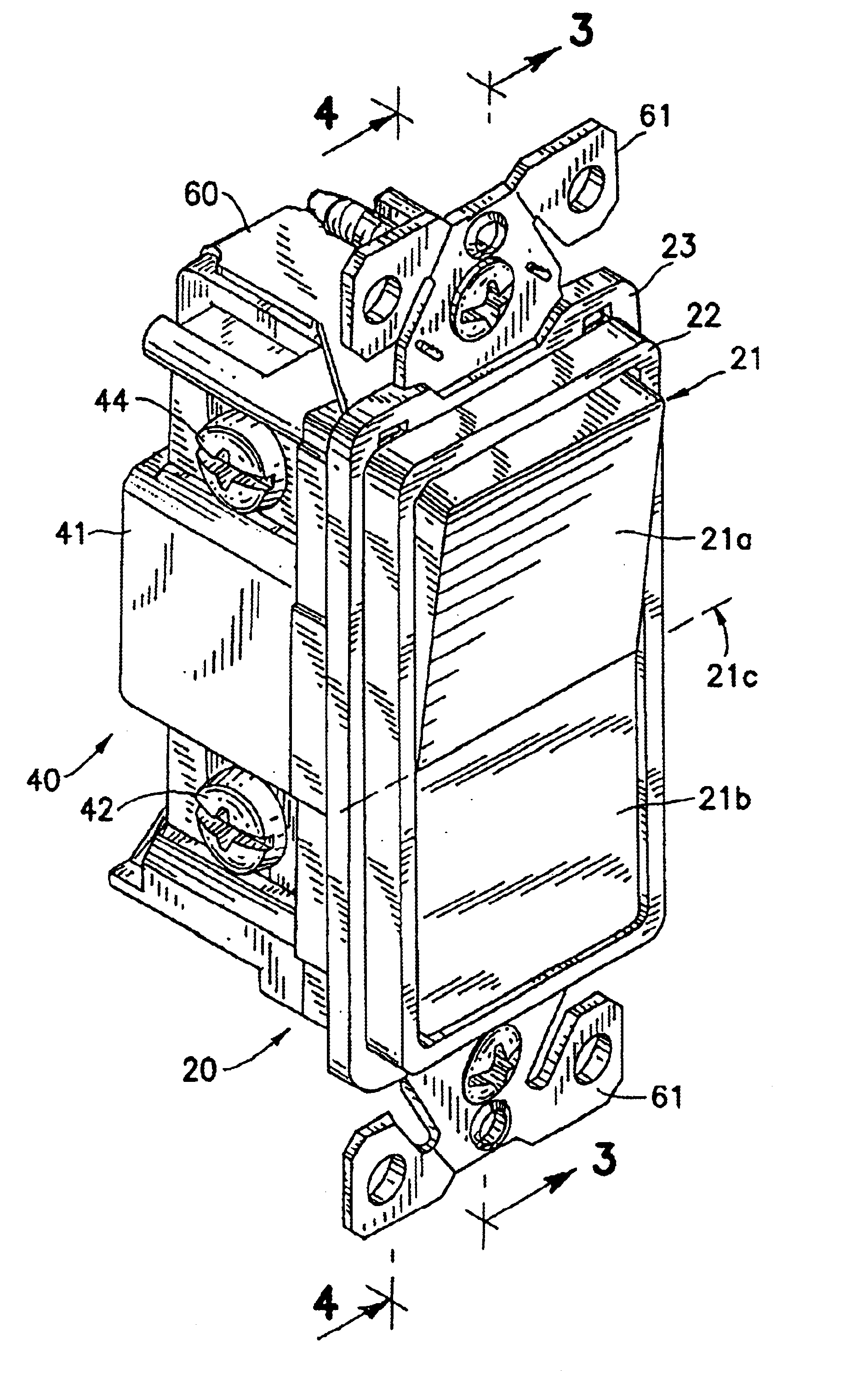
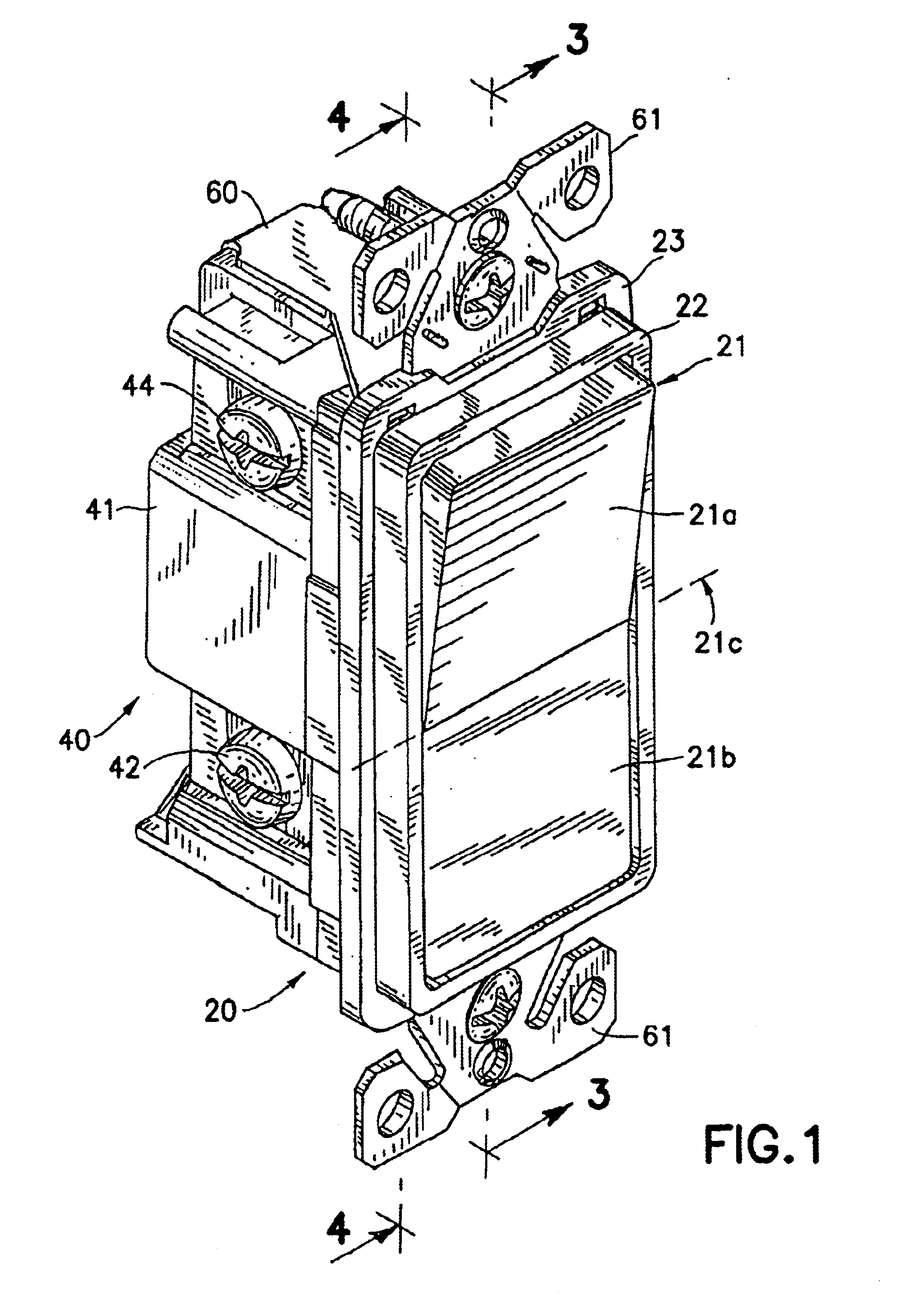
[0031]Referring to FIG. 1, an improved rocker-type switch in accordance with the present invention is shown in perspective, assembled view having a top housing part 20 mated with a bottom housing part 40 and secured together with an outer strap 60. The top housing part 20 has a toggle member 21 pivotable on a central pivot member (shown later) within a top housing frame 22 between up and down rocker positions. The toggle member is preferably formed with planar half sections 21a and 22b inclined slightly (about 6.5 degrees) with respect to each other on opposite sides of a center pivot axis (indicated by reference number 21c), with half section 21a shown in the...


PUM

PropertyMeasurementUnit
electrically insulativeaaaaaaaaaa
lengthaaaaaaaaaa
widthaaaaaaaaaa

Abstract

An improved rocker-type switch has a toggle member pivotably mounted on a central pivot member in a frame of a top housing part joined to a bottom housing part holding switch contacts in a modular block subassembly. A pair of movable contact arms is actuated by spring-biased actuator members held in the central pivot member. The modular block subassembly has an insulative top block member, a top switch contact plate with switch contacts on upright tabs inserted through slots in the top block member, an insulative bottom block member sandwiching the top switch contact plate, and a bottom switch contact plate having switch contacts on upright tabs inserted through slots in the bottom and top block members, forming a pair of opposing switch contact positions for the movable contact arms. The switch contact plates have clip portions for inserting the tabs of respective switch contact terminal plates therein. For different switch configurations, e.g., single-pole, double-pole, 3-way, or 4-way operation, the switch contact plates are changed, but the same block subassembly and other parts can be used, thereby minimizing change of the surrounding parts, limiting insulative molding costs, eliminating tolerance stack-up, and facilitating assembly through automation.

Description

TECHNICAL FIELD[0001]This invention generally relates to a rocker-type switch, and more particularly, to one that utilizes a modular block subassembly that allows a product line to use interchangeable switch contact elements for configuring single pole, double pole, 3-way, and 4-way switches with minimal changes to surrounding parts and elimination of tolerance stack up in the switch mechanism.BACKGROUND OF INVENTION[0002]The rocker-type electrical wall switch has long been known for its advantages of operating switch contacts through limited angular movement of a pivoted rocker, thus allowing the ends of the rocker to remain substantially flush in the rocker frame for aesthetics. U.S. Pat. No. 3,770,920 to Polliak disclosed a rocker-type switch in which the rocker is pivotally supported in a housing at a first pivot point, a movable plate supporting a contact brush is pivotally supported at a second pivot point in the housing, and a spring is compressed between a downwardly extendi...

Claims


Application Information

Patent Timeline
Patent Type & Authority Patents(United States)
IPC IPC(8): H01H11/00H01H9/00H01H23/12H01H3/00H01H21/02H01H23/00H01H21/00H01H15/00H01H23/20
CPCH01H23/205H01H11/00Y10T29/49105H01H2229/022
Inventor GOUHL, ERIK J.GALLAS, GUNTER A.MENDELSON, JAY J.RUSHANSKY, YULIY
Owner EATON INTELLIGENT POWER LIMITED
Why Eureka
Try Eureka