Combination umbrella and inverted bi-directional valve

a technology of bi-directional valves and umbrellas, which is applied in the direction of mechanical equipment, functional valve types, transportation and packaging, etc., can solve the problems of duckbill-umbrella combination valves that can leak, and the duckbill portion of the valve typically provides only limited flow prevention

Active Publication Date: 2007-07-17
VERNAY LAB
View PDF29 Cites 44 Cited by
  • Summary
  • Abstract
  • Description
  • Claims
  • Application Information

AI Technical Summary

Benefits of technology

[0007]The present invention also provides a combination valve including an inverted bi-directional valve portion and a resilient umbrella portion integrally formed with a valve body. A normally closed slit in the inverted bi-directional valve is responsive at a first predetermined fluid pressure in a first direction to permit transfer of fluid in the first direction. The umbrella valve portion prevents transfer of fluid in a first direction and is responsive at a second predetermined fluid pressure in a second direction to permit fluid flow in the second direction.
[0010]One advantage of the inventive combination fluid valve described herein is that the valve provides additional protection against leakage under low pressure conditions. The combination valve provides a delay in the onset of flow until there is sufficient pressure to flex the inverted bi-directional valve portion causing the slit to open. The inverted bi-directional valve causes standing fluid pressure below the opening threshold to maintain the slit in its closed position, until the applied pressure is increased sufficiently to cause the inverted bi-directional valve portion to flex and cause the slit to open thereby permitting flow through the open slit.

Problems solved by technology

However, the duckbill portion of the valve typically provides only limited prevention of flow in the dispensing direction and can leak under relatively low pressure differentials.
For example, duckbill-umbrella combination valves can leak when used in conjunction with containers of liquid that are inverted during use.

Method used


Image

  • Combination umbrella and inverted bi-directional valve
  • Combination umbrella and inverted bi-directional valve
  • Combination umbrella and inverted bi-directional valve

Examples


Embodiment Construction

[0021]All documents cited are, in relevant part, incorporated herein by reference; the citation of any document is not to be construed as an admission that it is prior art with respect to the present invention.

[0022]The embodiment disclosed below is not intended to be exhaustive or limit the invention to the precise form disclosed in the following detailed description. Rather, the embodiment is described so that others skilled in the art may utilize its teachings, but represents only certain manifestations of the invention.

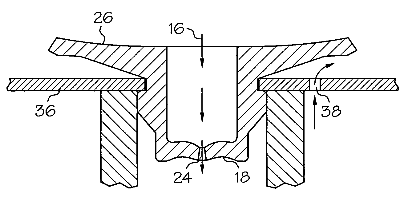
[0023]As used herein, the term “inverted bi-directional valve” refers to that portion of the combination valve having a structure similar to a conventional bi-directional valve except the flexing portion of the valve is inverted with respect to the substantially cylindrical portion. As a result, the inverted bi-directional valve described herein can be characterized as having a generally concave exterior surface, whereas a conventional bi-directional valve has a g...


PUM


Abstract

A combination valve including a valve body having an inverted bi-directional valve portion and an umbrella portion is disclosed. In accordance with one aspect of the invention, a combination valve includes a valve body with a substantially cylindrical portion defining a flow path, a resilient umbrella valve portion extending annularly from the valve body and an inverted bi-directional valve portion provided in the flow path. The inverted bi-directional valve portion includes an interior surface, an exterior surface and at least one normally closed slit extending therebetween, wherein the exterior surface of the inverted bi-directional valve portion includes a generally concave curved portion when the slit is closed.

Description

BACKGROUND OF THE INVENTION[0001]1. Field of the Invention[0002]The present invention relates to combination fluid valves, and in particular to combination valves comprising an inverted bidirectional valve in combination with an umbrella valve capable of providing flow responsive to changes in pressure differential.[0003]2. Description of the Related Art[0004]Current combination fluid valves include those of the duckbill-umbrella variety. Duckbill-umbrella combination valves allow fluid (often air) into a container or pump chamber via the umbrella valve portion along a first flow path and allow a second fluid (often a liquid product) out of the container or pump chamber via the duckbill valve portion through a second flow path. However, the duckbill portion of the valve typically provides only limited prevention of flow in the dispensing direction and can leak under relatively low pressure differentials. For example, duckbill-umbrella combination valves can leak when used in conjunc...

Claims


Application Information

Patent Timeline
Patent Type & Authority Patents(United States)
IPC IPC(8): F16K15/14A61M39/24B65D51/16F16K17/19
CPCA61M39/24B65D51/1644F16K15/148F16K17/19A61M2039/242A61M2039/2426Y10T137/7772Y10T137/778Y10T137/784Y10T137/7842
Inventor BAILEY, JAMES CHRISTOPHER
Owner VERNAY LAB
Why Eureka
Try Eureka