
High density RF connector system

a high-density rf connector and connector technology, applied in the direction of coupling contact members, coupling device connections, electric discharge lamps, etc., to achieve the effect of small outside diameter and convenient termination

Active Publication Date: 2007-07-17
ITT MFG ENTERPRISES LLC
View PDF16 Cites 2 Cited by
  • Summary
  • Abstract
  • Description
  • Claims
  • Application Information

AI Technical Summary

Benefits of technology

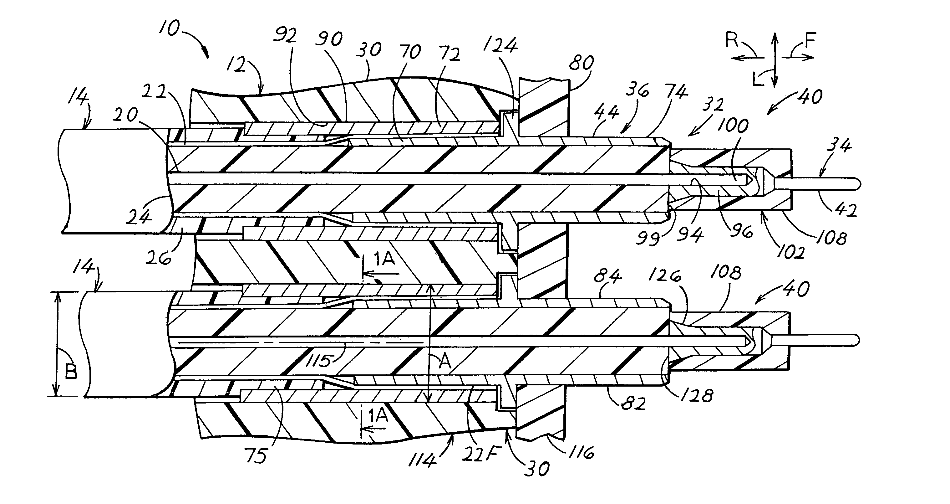
[0003]In accordance with one embodiment of the invention, a combination of a coax cable with inner and outer coax conductors and a coax contact pair comprising inner and outer contacts, is provided that enables the cable conductors to be easily terminated to the contacts, and with the combination having a small outside diameter that is only moderately greater than that of the coax cable alone. The insulative connector housing has a front face, and the outer contact has a front portion lying forward of the housing front face and having laterally opposite sides that are exposed, to be contacted. The housing has a forward projection that projects forward of said housing front face, that lies on longitudinally opposite sides of the outer contact front portion, and that has a front end that supports the inner contact.

Problems solved by technology

Also, on most circuit boards there is limited space so the contacts and mating contacts must be closely spaced.

Method used


Image

  • High density RF connector system
  • High density RF connector system
  • High density RF connector system

Examples


Embodiment Construction

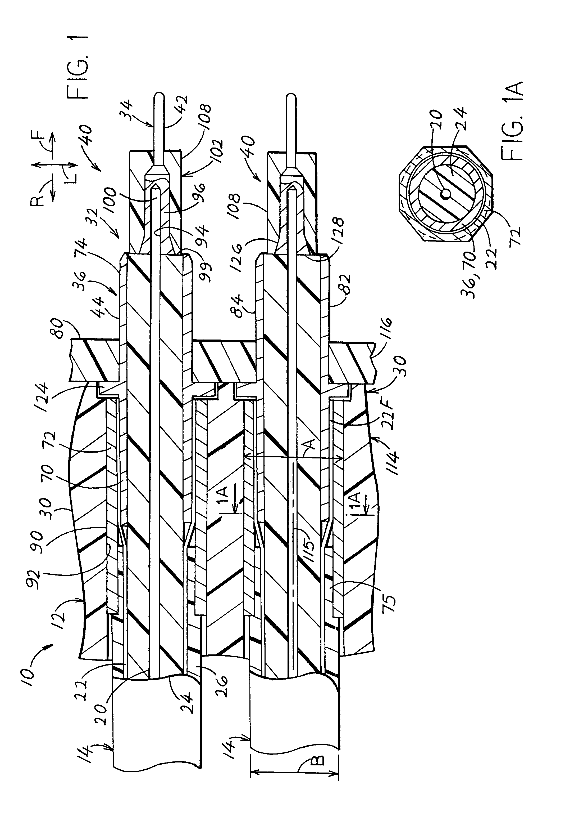
[0013]FIG. 1 illustrates a connector arrangement 10 which includes a coax connector 12 and a plurality of coax cables 14. Each coax cable includes inner and outer cable conductors 20, 22 and an insulator 24 lying between them. A jacket 26 lies around the outer cable conductor. The coax connector includes a housing 30 of dielectric, or insulative material, and a plurality of coax contact pairs 32 each lying in a housing passage 92 in the housing. Each coax contact pair includes an inner contact 34 that is connected to the inner cable conductor 20 and an outer contact 36 that is connected to the outer cable conductor 22. Each coax cable 14 and a coax contact pair 32 forms a combination 40.

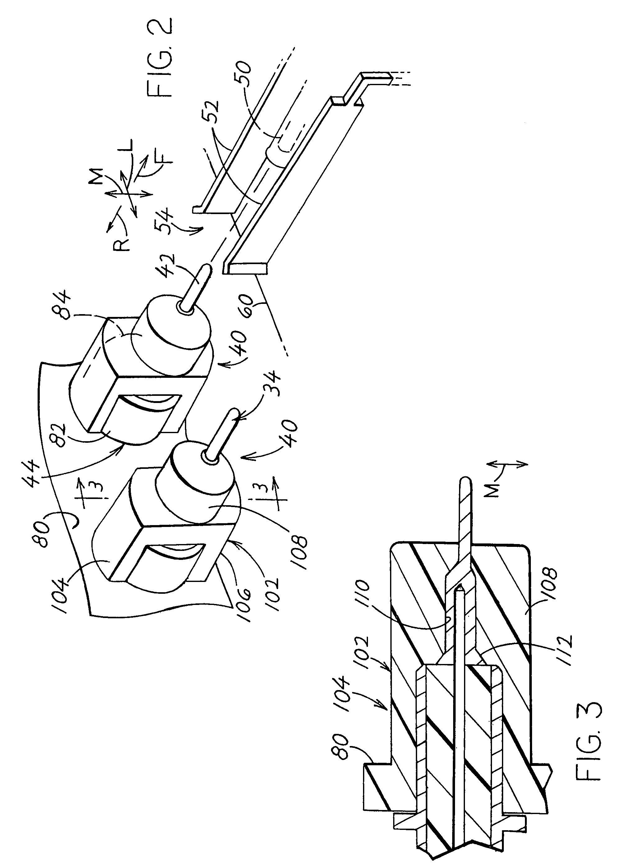
[0014]As shown in FIG. 2, the inner and outer contacts have mating front portions, or ends 42,44 that lie at the front of the connector and that are designed to engage, or mate, with inner and outer contact elements 50, 52 of a mating connector device 54. The outer contacts of the connector and conne...


PUM


Abstract

A coaxial connector has inner and outer contacts (34, 36) connected to inner and outer conductors (20, 22) of a coaxial cable (14), in a contact arrangement of small diameter (A), so each coax contact arrangements can carry high frequency signals. The outer contact has a rear portion (70) lying within the cable outer conductor (22) and locked in place by a crimp sleeve (72), and the outer contact has a front portion (74) that projects forward of a housing front face (80) and that has laterally opposite sides (82, 84) that are exposed to be contacted. The housing has a forward projection (102) with projection portions (104, 106) that lie on longitudinally (M) opposite sides of the outer contact front portion and that have projection front ends that merge and support the center contact (34) at a location forward of the outer conductor.

Description

CROSS-REFERENCE[0001]Applicant claims priority from U.S. Provisional patent application Ser. No. 60 / 702,390 filed Jul. 26, 2005.BACKGROUND OF THE INVENTION[0002]There is a need for a coaxial, or coax connector with multiple contact pairs for connecting to multiple coax cables. Each contact pair includes inner and outer contacts that connect, respectively, to the inner and outer conductors of a coax cable. Front ends of the contacts must be able to connect to mating contacts of a mating connector device, such as a connector device that lies on a circuit board. Each pair of contacts should be of small diameter so it can carry high frequency signals. Also, on most circuit boards there is limited space so the contacts and mating contacts must be closely spaced. A coax connector with contact pairs of simple and compact construction and mounting, would be of value.SUMMARY OF THE INVENTION[0003]In accordance with one embodiment of the invention, a combination of a coax cable with inner and...

Claims


Application Information

Patent Timeline
Patent Type & Authority Patents(United States)
IPC IPC(8): H01R33/945H01R13/646
CPCH01R9/038H01R9/0518H01R13/4364H01R24/50H01R13/26H01R13/567H01R2103/00H01R13/65918
Inventor GHERARDINI, STEPHEN DANIEL
Owner ITT MFG ENTERPRISES LLC
Learn More