Stackable multiple support arm for electronic devices

a technology for electronic devices and mounting apparatuses, applied in the direction of revolving cabinets, machine supports, building scaffolds, etc., can solve problems such as becoming an unnecessary obstruction

Inactive Publication Date: 2007-07-24
INNOVATIVE OFFICE PROD LLC
View PDF11 Cites 113 Cited by
  • Summary
  • Abstract
  • Description
  • Claims
  • Application Information

AI Technical Summary

Problems solved by technology

However, where a longer support pole is provided, it may not always be needed thereby becoming an unnecessary obstruction.

Method used


Image

  • Stackable multiple support arm for electronic devices
  • Stackable multiple support arm for electronic devices
  • Stackable multiple support arm for electronic devices

Examples


Embodiment Construction

[0022]In describing the preferred embodiments of the invention illustrated in the drawings, specific terminology will be used for the sake of clarity. However, the invention is not intended to be limited to the specific terms so selected, and it is to be understood that each specific term includes all technical equivalents that operate in a similar manner to accomplish a similar purpose.

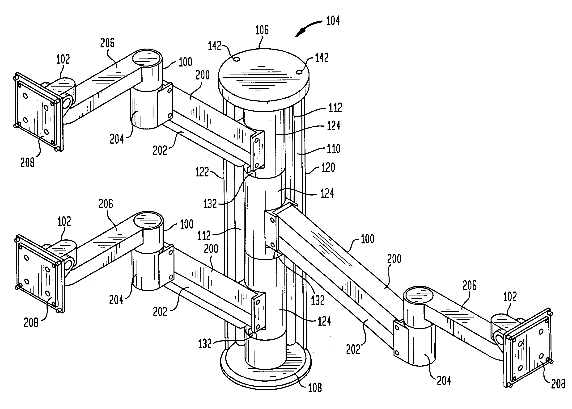
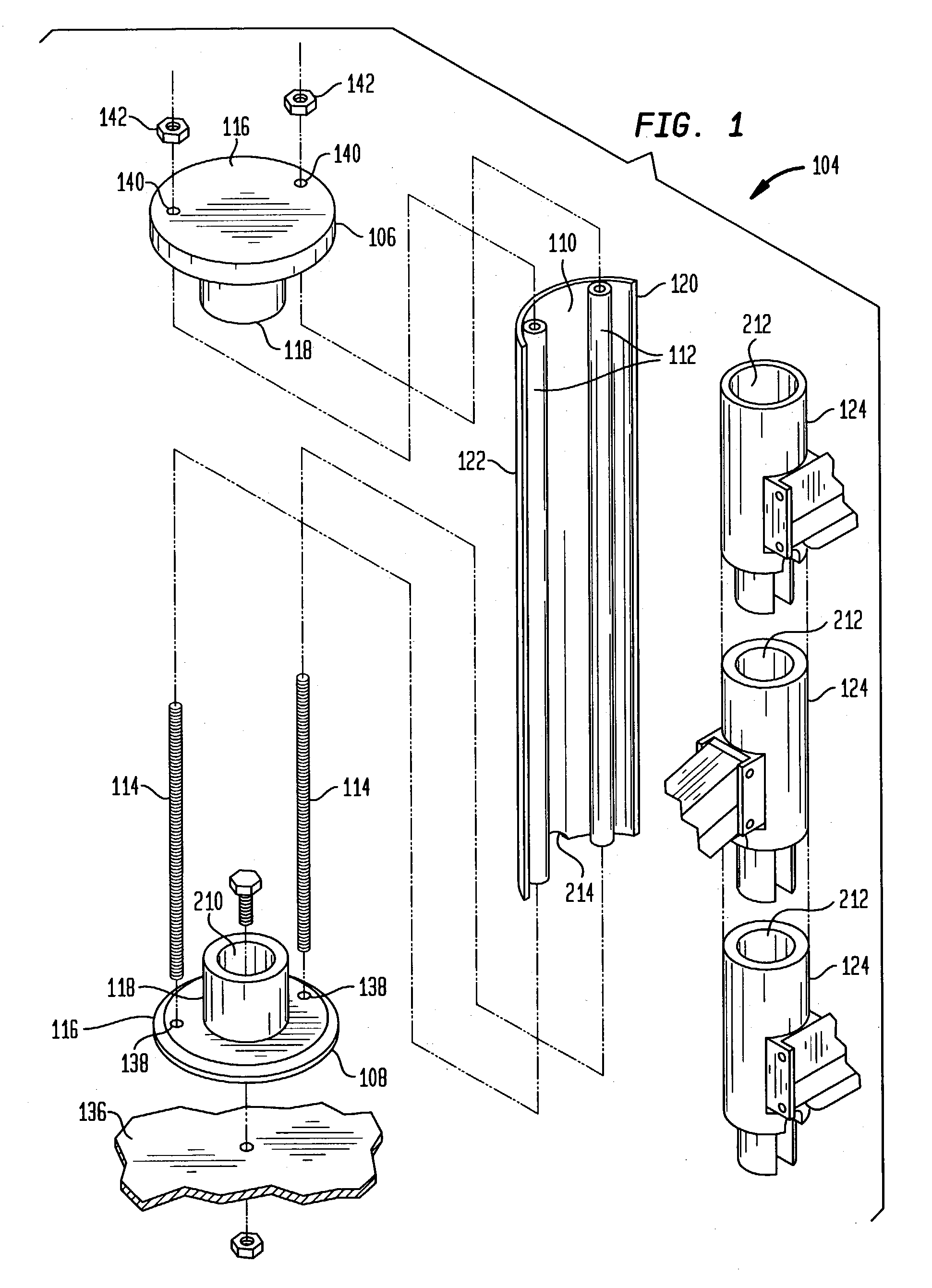
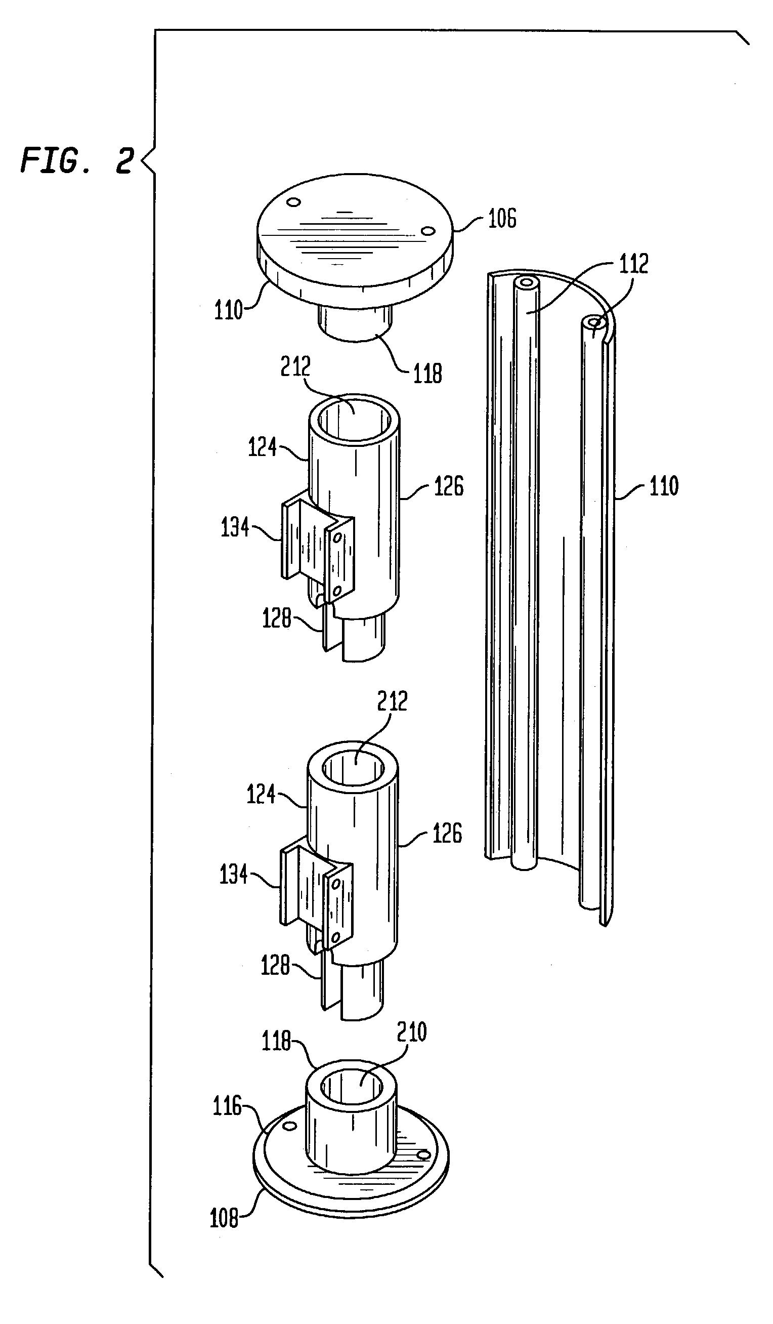
[0023]Referring now to the drawings, wherein like reference numerals represent like elements, there is shown in FIGS. 1 and 5 a system in the nature of a mounting apparatus for supporting a plurality of electronic devices, and generally designated by reference 104.

[0024]As best shown in FIG. 5, there is disclosed a plurality of securing means in the nature of support arm assemblies generally designated by reference 100 which are attached to the mounting apparatus 104. Suitable arm assemblies 100 for the purposes of the present invention are disclosed in Applicant's U.S. Pat. Nos. 6,478,274 and 6,409,...


PUM


Abstract

A mounting apparatus includes a plurality of arm mounts which are rotationally coupled in a vertical column in end to end relationship to provide a nested arrangement thereof. A support arm is attached to each of the arm mounts to which an electronic device is attached. The arm mounts are secured in nested arrangement between a pair of mounting plates which engage the ends of an elongated shield at least partially surrounding the arm mounts.

Description

CROSS REFERENCE TO RELATED APPLICATIONS[0001]The present application claims the benefit of Provisional Application No. 60 / 377,049, filed on May 1, 2002, entitled “Stackable Multiple Support Arm for Electronic Devices”, the disclosure of which is incorporated herein by reference.[0002]The present invention relates in general to a modular mounting system for stacking a plurality of adjustable mounting or support arms in a vertical column for supporting an electronic device.[0003]Various electronic devices such as LCD flat screen displays, CRT displays, computer keyboards, laptop computers, plasma displays and the like are used in a variety of residential, commercial and industrial applications. By way of example, an LCD display is often coupled to a computer or server for displaying information such as text and / or graphic images. There are a number of applications where it is desirable to mount two or more flat screen displays or other electronic devices in close proximity to each oth...

Claims


Application Information

Patent Timeline
Patent Type & Authority Patents(United States)
IPC IPC(8): E04G3/00A47B49/00A47B81/06F16M11/12F16M13/02
CPCA47B49/00A47B81/065F16M11/10F16M11/12F16M11/2014F16M11/2092F16M11/24F16M13/02F16M2200/063Y10S248/917
Inventor ODDSEN, JR., ODD N.
Owner INNOVATIVE OFFICE PROD LLC
Why Eureka
Try Eureka