Method of allocating bandwidth on request to the stations of a local area network

a local area network and bandwidth allocation technology, applied in the field of bandwidth management, can solve the problems of csma/cd protocol, drastic limitations in its ability to take advantage of the intrinsic performance of shared transmission, and inability to meet the requirements of bandwidth allocation

Inactive Publication Date: 2007-07-24
IBM CORP
View PDF4 Cites 2 Cited by
  • Summary
  • Abstract
  • Description
  • Claims
  • Application Information

AI Technical Summary

Problems solved by technology

However, two stations can start transmitting at the same time, causing a collision.
Although Ethernet does not set an upper limit to the number of stations that can be connected on a same transmission medium there are, in practice, drastic limitations.
Generally speaking, as more users are added to a shared network or, as applications requiring more data are added, performance inevitably deteriorates.
Thus, yet simple, CSMA / CD protocol, suffers drastic limitations in its ability to take advantage of the intrinsic performance of the shared transmission medium i.e., 10 Mbps in this example.
Further increasing the number of users (and therefore packet transmissions) creates an even higher collision potential.
This tends to add a considerable overhead, severely impacting performance, until the mechanism just collapses when medium is attempted to be too much utilized.
But, even though the above system prevents the collisions between stations from happening, it does not prevent a station from monopolizing the bandwidth while the other stations cannot transmit.
Unfortunately, the need of a station varies during the time.
If a station is configured with a static credit of bytes which is too low for running an application, this one will experience some problems (jitter, lost packets .
Conversely, if the station is configured with a high credit of bytes, the application will work correctly but the station will keep a high credit, even after the application has been ended, resulting in a part of bandwidth which is no more used and cannot be used by the other stations of the logical ring.

Method used


Image

  • Method of allocating bandwidth on request to the stations of a local area network
  • Method of allocating bandwidth on request to the stations of a local area network
  • Method of allocating bandwidth on request to the stations of a local area network

Examples


Embodiment Construction

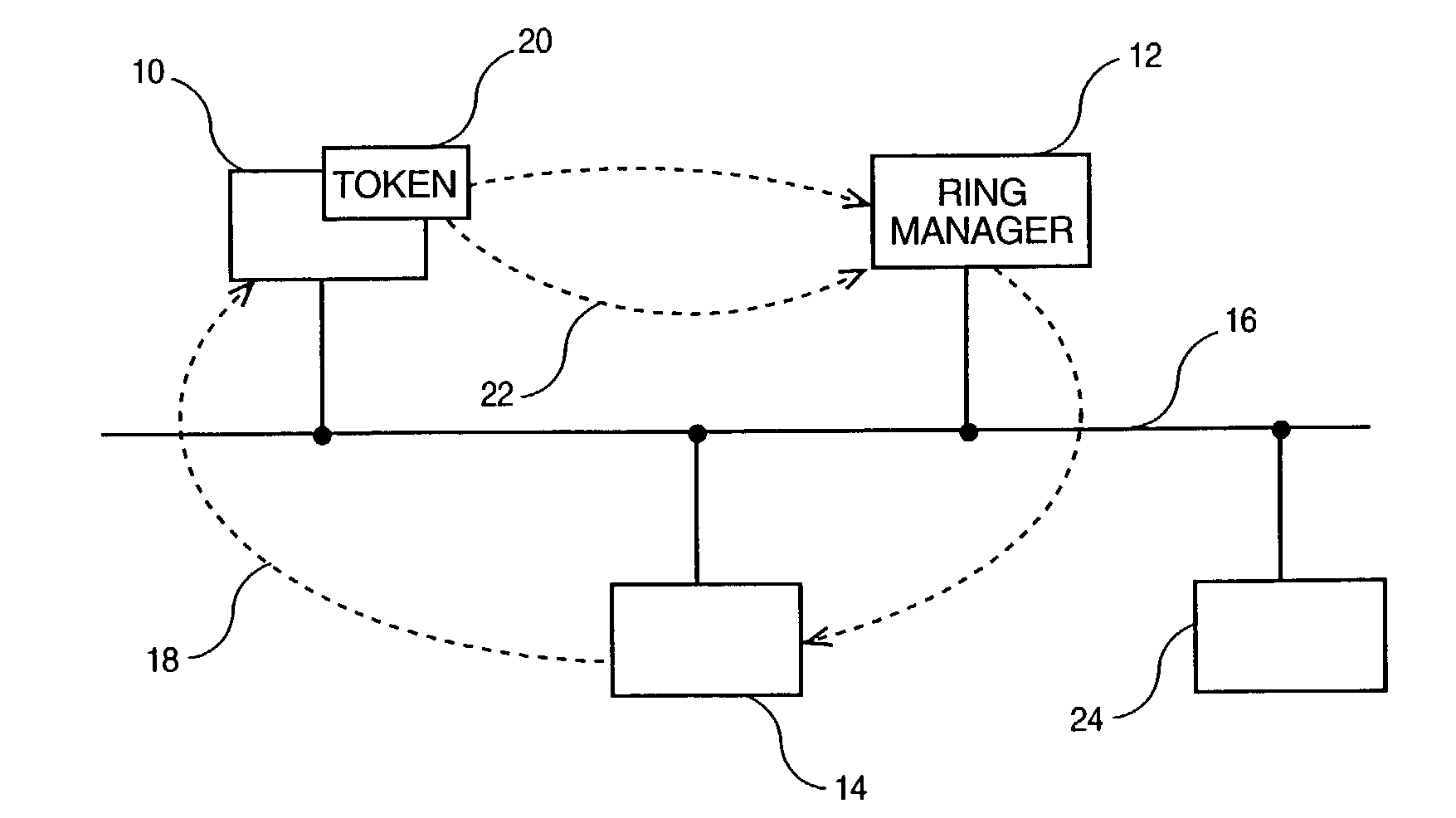
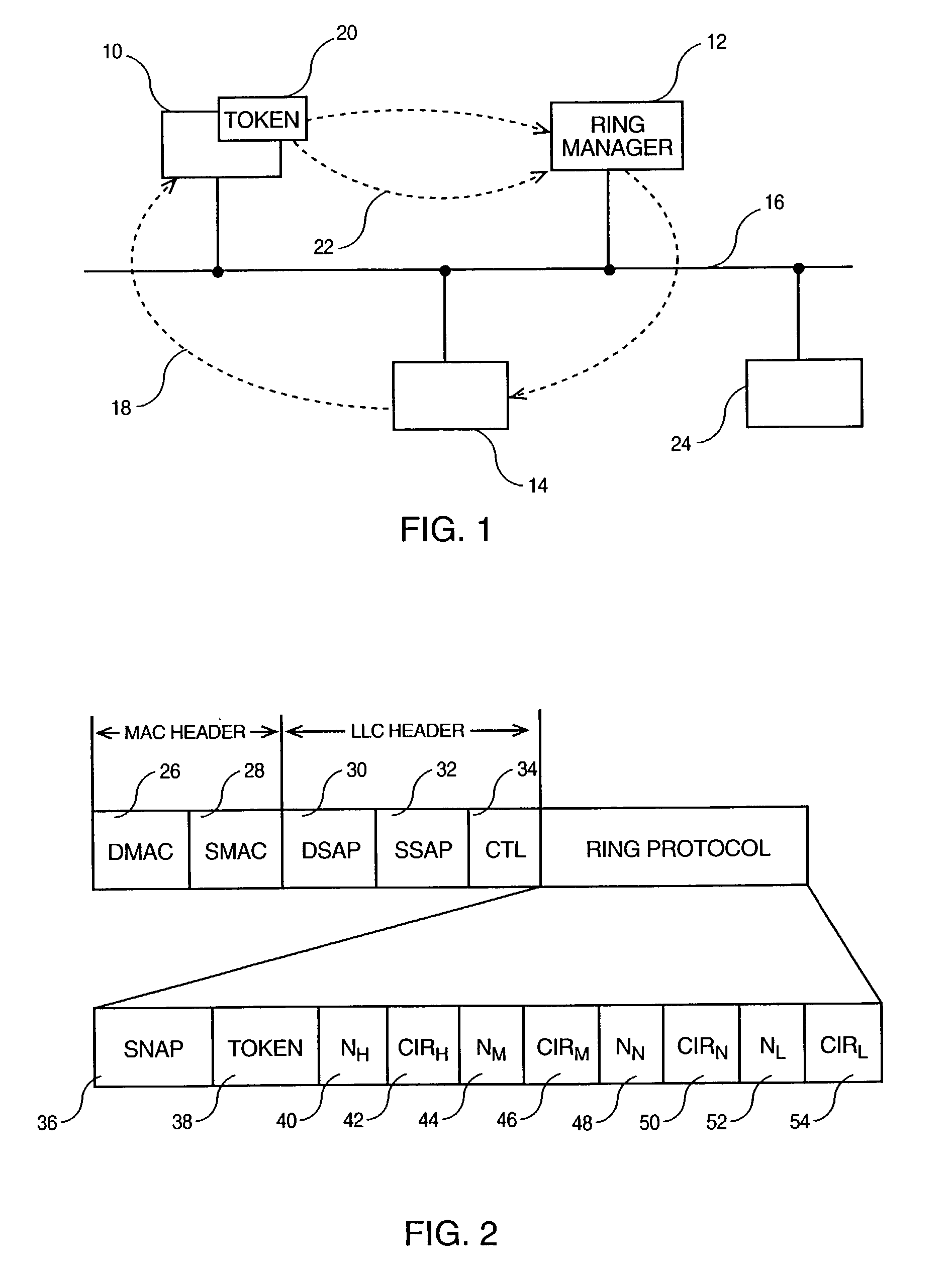
[0015]According to FIG. 1, an Ethernet LAN includes several stations 10, 12 and 14 physically connected on the shared medium 16, exactly as with a regular collision Ethernet LAN, and organized so that they form a logical ring 18. This is achieved through the circulation of a token 20 which takes the form of a special Ethernet frame, forwarded 22 from one station to a next one, e.g., from station 10 to station 12.

[0016]It is worth noting here that not all stations connected on the same LAN segment need to participate into the collision-free ring 18 thus formed. The invention assumes that both types of protocols (collision and collision-free) may coexist at any given instant so that a station like 24 needs not to implement the new protocol while still being able to communicate with all the others connected on the shared transmission medium 16 however, using the regular collision protocol.

[0017]It must also be noted that one of the stations whithin the ring, for example the station 12,...


PUM


Abstract

A method of bandwidth management enabling to insure a guaranteed bandwidth to each station of transmission network comprising a plurality of stations (10, 12, 14) forming a logical ring wherein a token frame is circulating from station to station, each station being allowed to transmit a credit (c) of data bytes upon reception of the token frame wherein the credit is increased in proportion to a variable TRTT standing for Token Round Trip Time which is the time taken for the token frame to circulate around the logical ring since the preceding reception of the token frame by the station. The credit is increased in proportion of a variable CIR standing for Committed Information Rate which is the guaranteed transmission rate that the station can use to transmit data wherein the value of CIR is determined by a class of bandwidth which has been previously selected by the station upon the preceding reception of the token frame by the station.

Description

TECHNICAL FIELD[0001]The present invention relates to the bandwidth management between the stations in a data transmission network of the Ethernet type and relates particularly to a method of allocating bandwidth on request to the stations of a Local Area Network such as Ethernet network.BACKGROUND[0002]On local Area Networks (LANs) of the Ethernet type able to transmit the data at speeds higher than one gigabit / s, an unlimited number of stations can be connected to a shared medium. To control the exchange of data between the stations connected on the shared medium, Ethernet uses a protocol called Carrier Sense, Multiple Access Collision Detect (CSMA / CD). The “Multiple Access” part means that every station is indeed connected to the shared medium forming a single data path. The “Carrier Sense” part means that before transmitting data, a station checks it to see if any other station is already sending something. If the transmission medium appears to be idle then, the station can actu...

Claims


Application Information

Patent Timeline
Patent Type & Authority Patents(United States)
IPC IPC(8): H04L12/42H04L12/423H04L47/22H04L47/36
CPCH04L12/423H04L47/10H04L47/225H04L47/24H04L47/283H04L47/36H04L47/39
Inventor DENECHEAU, LIONELESTEVE, DENISSICSIC, PATRICK
Owner IBM CORP
Why Eureka
Try Eureka