
Receiving frame having removable computer drive carrier and lock

Inactive Publication Date: 2007-07-31
KINGSTON DIGITAL CO LTD
View PDF4 Cites 53 Cited by
  • Summary
  • Abstract
  • Description
  • Claims
  • Application Information

AI Technical Summary

Benefits of technology

[0010]A microcontroller is located on the receiving frame and responsive to the position of the locking pawl in the locked and unlocked positions to prevent a manual shutdown of the drive when the drive carrier has been locked within its receiving frame. The microcontroller is also adapted to generate visual status indicator signals when the drive is spun-up and ready to be accessed by the host computer, when the drive is spun-down and ready to be removed with its carrier from the receiving frame, when a cooling fan on the receiving frame malfunctions, or when the drive fails to receive power. The microcontroller is still further adapted to generate a visual warning signal in the event that a SAS (serial attached SCSI) drive has been inserted into a SATA (serial ATA) receiving frame. The microcontroller prevents such a SAS drive from being powered-up to avoid a potential overheating condition and a corresponding thermally induced system failure.

Problems solved by technology

Because of its removable nature, it is possible for an unauthorized individual to withdraw the computer drive carrier from its receiving frame without being detected.
In this case, sensitive computer data could become lost and / or stolen.
Occasionally, a computer drive carrier will transport a SAS computer drive that is known to be incompatible with a SATA receiving frame.
When such a computer drive is located in a SATA receiving frame, an overheating condition may result.
In the event the overheating condition is not corrected early, some or all of the system could be exposed to a thermally induced failure.

Method used


Image

  • Receiving frame having removable computer drive carrier and lock
  • Receiving frame having removable computer drive carrier and lock
  • Receiving frame having removable computer drive carrier and lock

Examples


Embodiment Construction

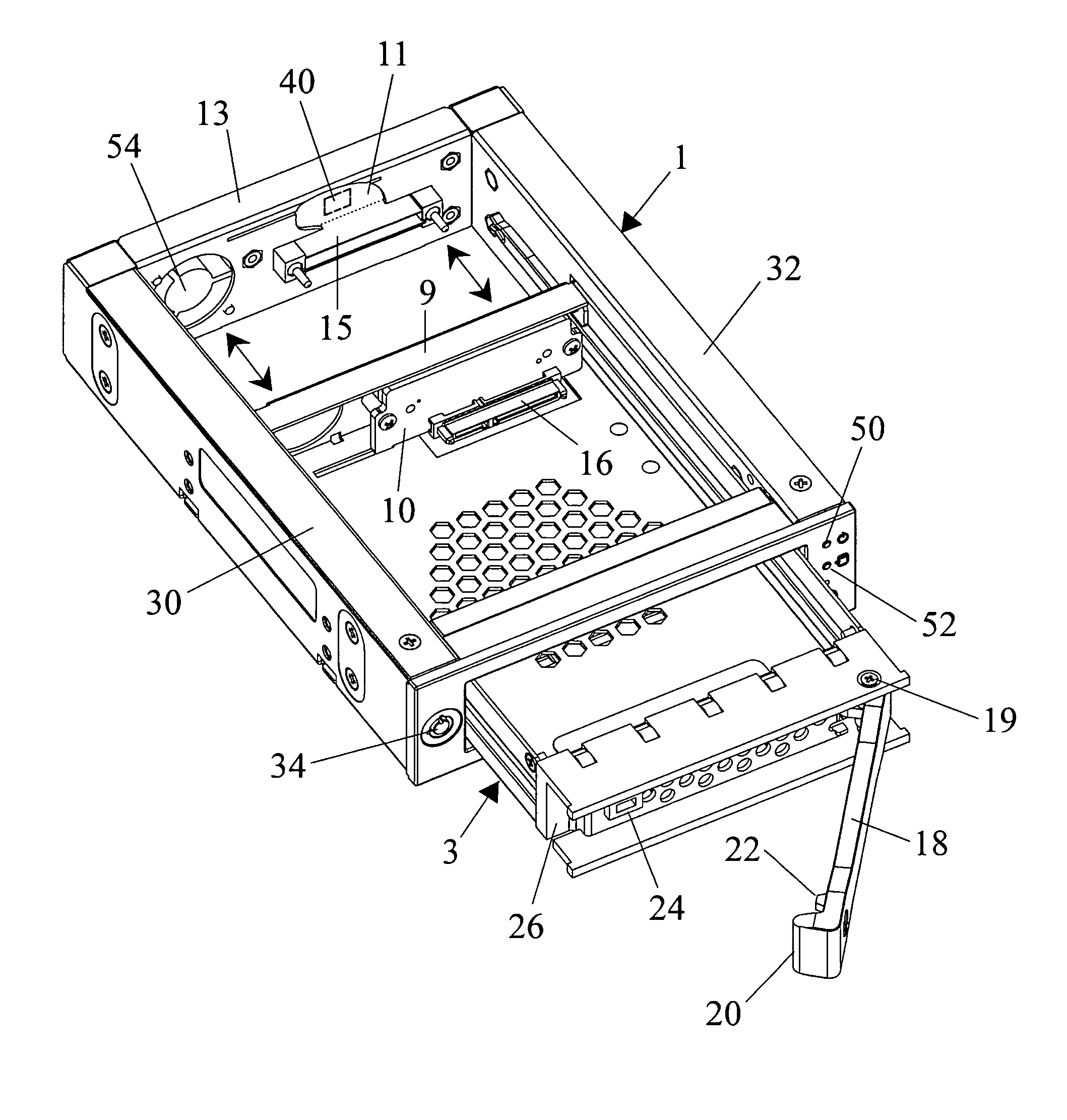
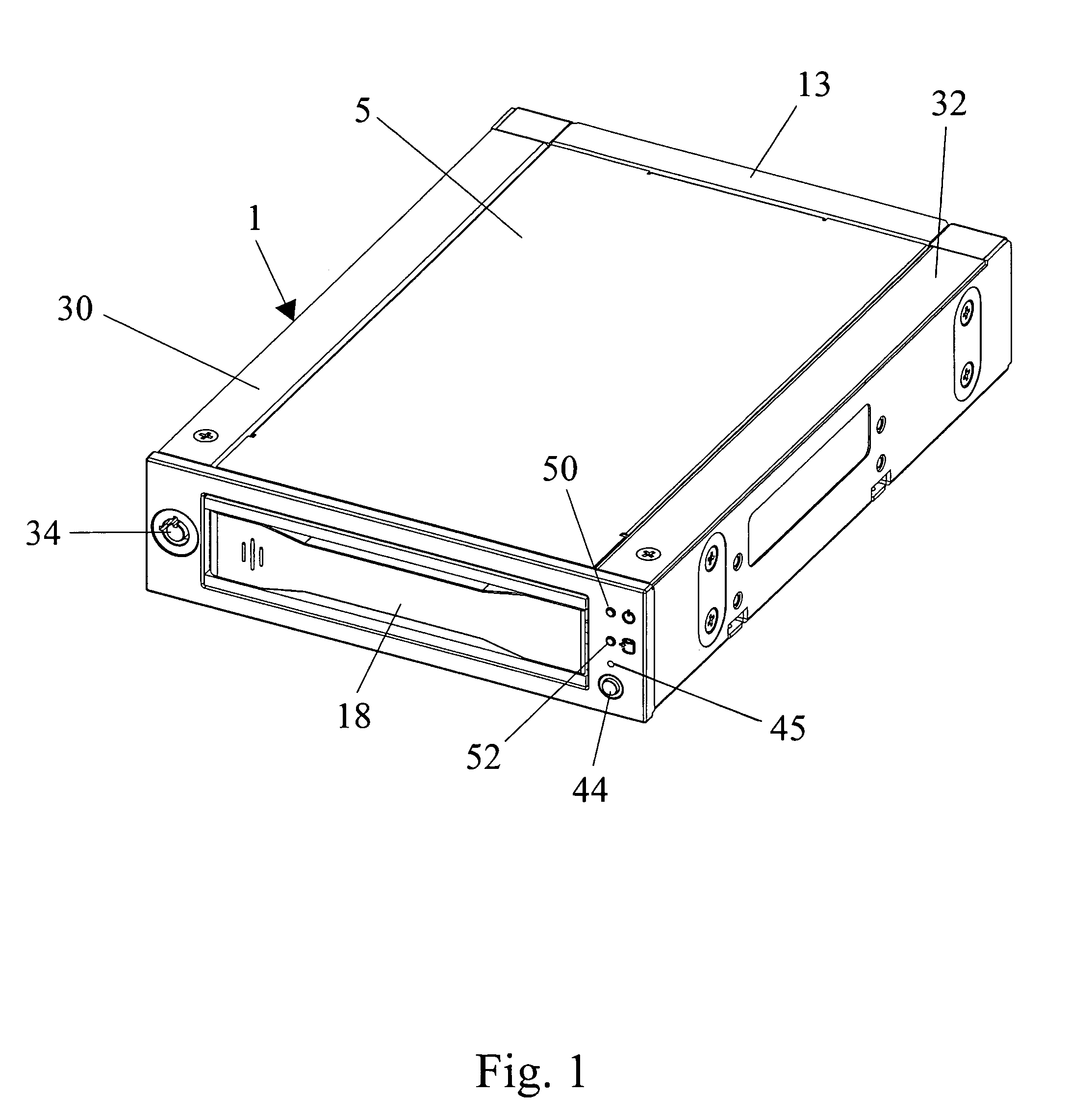
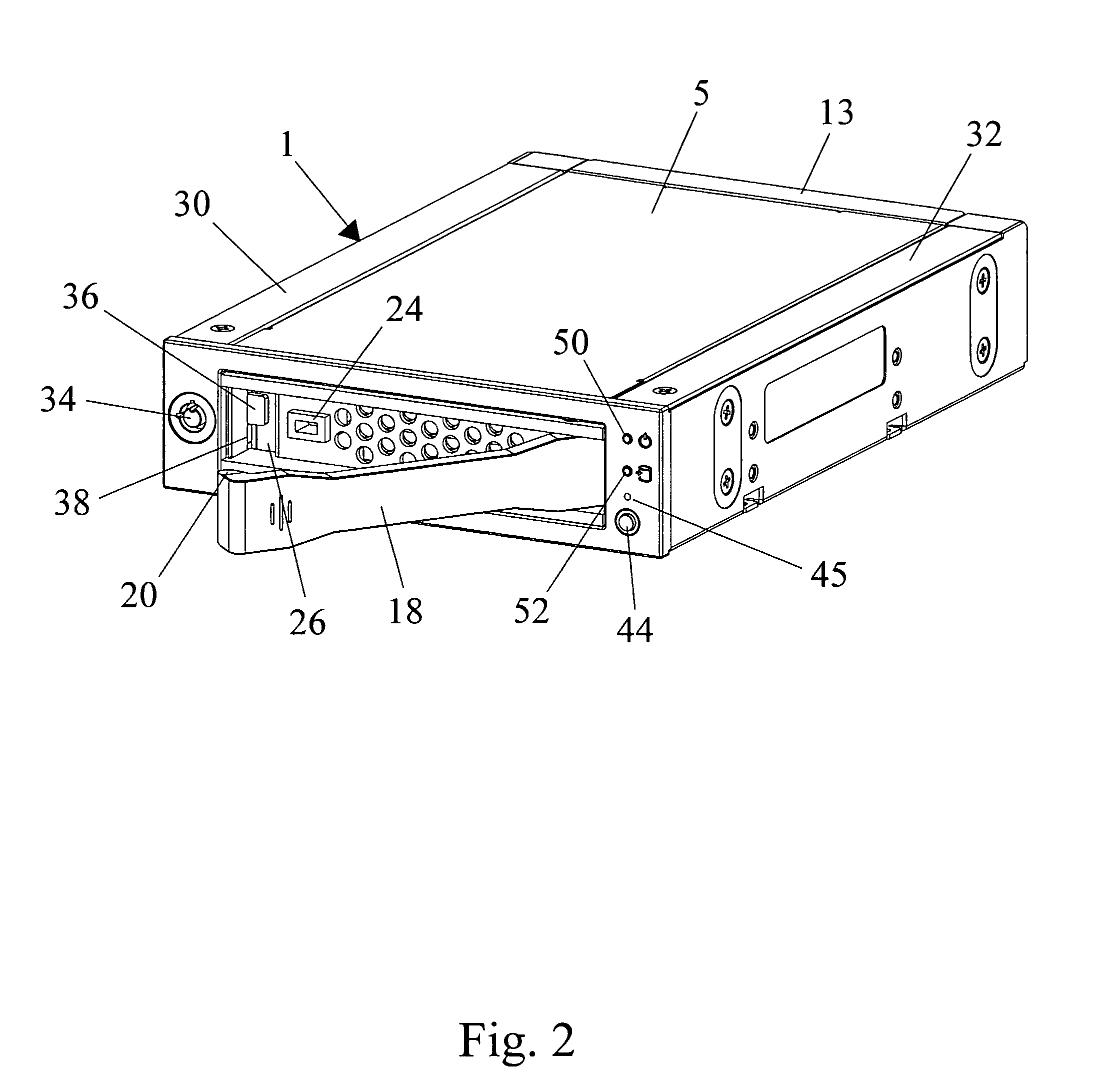
[0015]Referring concurrently to FIGS. 1-4 of the drawings, there is shown a (e.g., rectangular) receiving frame 1 having an opening through the front for receiving therewithin a removable computer drive carrier (designated 3 in FIG. 3). The opposite sides 30 and 32 of receiving frame 1 are hollow for a purpose that will soon be described. The computer drive carrier 3 encloses a standard computer drive (not shown) such as a disc drive, or the like. The receiving frame 1 is typically mounted in a computer drive bay or similar enclosure (also not shown) by which the computer drive that is enclosed within the drive carrier 3 can be interfaced with and accessed by a host computer. A cover 5 extends across the top of the receiving frame 1 to enclose the computer drive carrier 3 therewithin. The carrier 3 is slidable into and out of receiving frame 1 to enable the computer drive to be transported from place-to-place and / or to be replaced by a different drive.

[0016]As is best shown in FIGS....


PUM


Abstract

A computer drive carrier to be removably received within a receiving frame so that a computer drive transported by the carrier can be interfaced with a host computer. A handle is pivotally connected to the computer drive carrier and adapted to be rotated between a closed position when the carrier is received within the receiving frame and an open position when it is desirable to remove the carrier and its drive from the receiving frame to be replaced by a different carrier. A key controlled lock is mounted on the receiving frame and includes a locking pawl that is rotatable from an unlocked position, at which to permit the handle to be rotated from the closed position to the open position so that the computer drive carrier can be removed from its receiving frame, to a locked position, at which to prevent the handle from being rotated to the open position so that the computer drive carrier is locked in place in the receiving frame. A microcontroller is located on the receiving frame and responsive to when a SAS computer drive has been inserted within a SATA receiving frame so as to initiate a LED warning signal to indicate a potential overheating condition. The microcontroller also prevents a manual shutdown of the computer drive when the drive carrier is locked within its receiving frame.

Description

BACKGROUND OF THE INVENTION[0001]1. Field of the Invention[0002]This invention relates to a receiving frame interfaced with a host computer to removably receive a computer drive carrier in which a computer drive is transported and to a locking system to prevent a removal of the carrier from its receiving frame. A microcontroller is located on the receiving frame to be interfaced with the locking system to prevent a manual shutdown of the drive when the drive carrier is locked within its receiving frame and to generate a visual warning signal in the event that a SAS drive has been inserted into a SATA receiving frame.[0003]2. Background Art[0004]With the advent of personal computers and workstations, it is often necessary to remove the medium on which computer data is stored. For example, it may be desirable to remove a storage medium so as to be carried to a different location and / or to a different computer system. It may also be desirable to remove the storage medium to a secure lo...

Claims


Application Information

Patent Timeline
IPC IPC(8): G06F1/16
CPCG06F1/187
Inventor PAUL, DIETER G.TANG, CHOON-TAK
Owner KINGSTON DIGITAL CO LTD
Learn More