Pressure-based fuel metering unit

a fuel metering unit and pressure-based technology, applied in the direction of machines/engines, transportation and packaging, liquid transfer devices, etc., can solve the problems of high cost, long lead time, and high cost of components, and achieve the effect of reducing the cost of components

Active Publication Date: 2007-08-07
HAMILTON SUNDSTRAND CORP
View PDF3 Cites 34 Cited by
  • Summary
  • Abstract
  • Description
  • Claims
  • Application Information

AI Technical Summary

Benefits of technology

[0005]A fuel delivery system for use, for example in a gas turbine engine system, includes a fuel metering unit including a main fuel inlet. The fuel metering unit includes fuel pressure and temperature sensors. A cavitating venturi is in fluid communication with the main fuel inlet and includes venturi characteristics such as throat diameter. A fuel nozzle is in fluid communication with the venturi for delivering fuel to the gas turbine engine. A controller is connected to the pressure and temperature sensors and is operable to calculate a flow rate of fuel through the nozzle based upon the signals from the pressure and temperature sensors and the fuel and venturi characteristics. In this manner, the fuel metering valve, linear variable displacement transducer, and other components of a typical fuel delivery system may be eliminated.
[0006]The cavitating venturi may be variable in nature in that an axially adjustable needle may be arranged within the throat to vary the area in the throat thereby adjusting the flow rate through the venturi based upon the resultant area. The variably adjustable venturi may be passive in nature by utilizing a spring, or active in nature by utilizing, for example, piezoelectric actuators. The cavitating venturi can also be used at the fuel nozzle to further simplify the fuel delivery system.
[0007]Accordingly, the present invention provides a pressure-based fuel metering unit that eliminates the fuel metering valve, linear variables displacement transducer, and other complicated and expensive components typically found in prior art fuel delivery systems.

Problems solved by technology

Fuel delivery systems for gas turbine engines are expensive and include numerous complex parts.
The matched valves, linear variable displacement transducers, and other components, are all quite complicated and prone to high rates of rejection due to their complexity.
These components also have high costs and long lead times. Therefore, what is needed is a pressure-based fuel metering unit that eliminates the fuel metering valve, linear variable displacement transducer, and other complicated and expensive components.

Method used


Image

  • Pressure-based fuel metering unit
  • Pressure-based fuel metering unit
  • Pressure-based fuel metering unit

Examples


Embodiment Construction

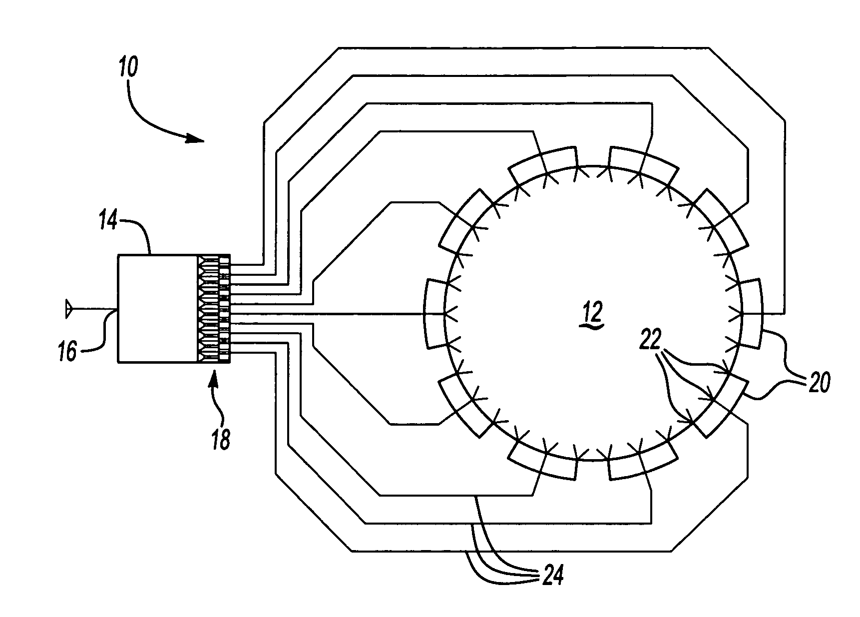
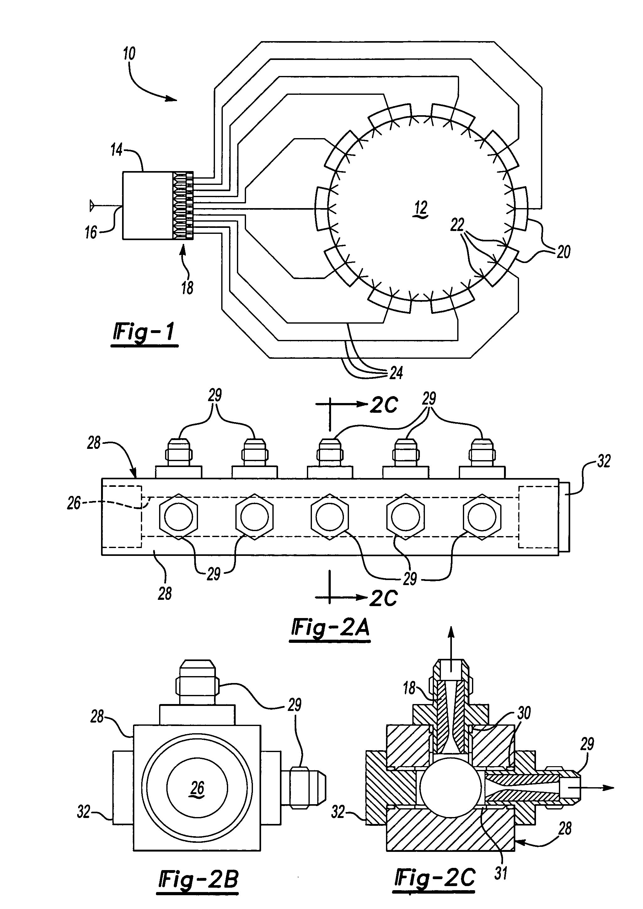
[0021]A fuel delivery system 10 is shown schematically in FIG. 1. The system 10 is preferably for use in delivering fuel to a gas turbine engine 12. A fuel metering unit 14 receives fuel through a main fuel inlet 16 and delivers the fuel to inventive cavitating venturis 18 that act as flow dividers. The cavitating venturis 18 replace the fuel metering valve and several other components typically used to deliver fuel to the engine 12, as will be appreciated from the discussion below.

[0022]Each of the cavitating venturis 18 delivers fuel to a manifold 20 that has multiple nozzles 22. The nozzles 22 spray fuel into the engine 12 in a desired manner, as is well known in the art. The cavitating venturis 18 are connected to the manifolds 20 by fuel lines 24. The fuel delivery system 10 shown in FIG. 1 is only exemplarily and may be modified, as would be appreciated by one of ordinary skill.

[0023]One example arrangement of multiple cavitating venturis 18 is shown in FIGS. 2A-2C. The ventur...


PUM


Abstract

A fuel delivery system for use, for example in a gas turbine engine system, includes a fuel metering unit including a main fuel inlet. The fuel metering unit includes fuel pressure and temperature sensors. A cavitating venturi is in fluid communication with the main fuel inlet and includes venturi characteristics such as throat diameter. A fuel nozzle is in fluid communication with the venturi for delivering fuel to the gas turbine engine. A controller is connected to the pressure temperature sensors and is operable to calculate a flow rate of fuel through the nozzle based upon the signals from the pressure and temperature sensors and the fuel and venturi characteristics. A variable cavitating venturi may be arranged within the throat to vary the area and adjust the flow rate through the venturi. The cavitating venturi can also be used at the fuel nozzle to further simplify the fuel delivery system.

Description

BACKGROUND OF THE INVENTION[0001]This invention relates to a fuel delivery system suitable for a gas turbine engine. The invention uses a cavitating venturi to deliver and meter the fuel to the turbine and simplify the system.[0002]Fuel delivery systems for gas turbine engines are expensive and include numerous complex parts. The fuel delivery system is controlled by scheduling fuel flow as a function of an electronic engine controller (EEC) command based upon a fuel metering valve position and a linear variable displacement transducer used to provide feedback.[0003]Conventional fuel controls use a precision-matched fuel metering valve, which is displaced along its axis by servo pressure. A linear variable displacement transducer is used to determine the exact position of the valve, which, in turn, implies its full capacity at that specific displacement. The fuel metering valve does not close off so that it is leak tight, thereby requiring that another minimum pressure and shut-off ...

Claims


Application Information

Patent Timeline
Patent Type & Authority Patents(United States)
IPC IPC(8): F02C9/26B67D7/16
CPCF02C7/228
Inventor PARADISE, BRUCE
Owner HAMILTON SUNDSTRAND CORP
Why Eureka
Try Eureka