Dynamic shock detection in disk drive using hair trigger timer

a technology of disk drive and timer, which is applied in the direction of instruments, magnetic disk recording, record information storage, etc., to achieve the effect of longer running time and better protection

Inactive Publication Date: 2007-08-07
MAXTOR
View PDF28 Cites 16 Cited by
  • Summary
  • Abstract
  • Description
  • Claims
  • Application Information

AI Technical Summary

Benefits of technology

[0014]In one embodiment, the position error of the transducer head with respect to a target track is monitored, and where a large deviation from the centerline of the target track is observed, a severe shock is inferred and a severe shock timer is activated and enables a write fault to prohibit write operations while it is running. The severe shock timer supplements a normal shock timer triggered by smaller shock events. The severe shock timer also has a much longer running time than the normal shock timer. The long running time allows oscillations or ringing in the disk drive to dampen and disappear before the write operations are attempted again. In addition, because the ringing following a severe shock event has a relatively low frequency, the long delay introduced by the severe shock timer prevents the disk drive from repeatedly cycling between an off-track state in which writing is prohibited due to the normal shock timer and an on-track state which may be entered as the transducer head passes through the track centerline.
[0015]In another embodiment, shock events following an initial shock event more easily trigger a write fault. In response to a shock event, the shock threshold is lowered for a predetermined time period. Because shock events commonly occur in closely spaced intervals, the disk drive quickly responds to subsequent small shock events to better protect against track misregistration errors.

Problems solved by technology

In addition, because the ringing following a severe shock event has a relatively low frequency, the long delay introduced by the severe shock timer prevents the disk drive from repeatedly cycling between an off-track state in which writing is prohibited due to the normal shock timer and an on-track state which may be entered as the transducer head passes through the track centerline.

Method used


Image

  • Dynamic shock detection in disk drive using hair trigger timer
  • Dynamic shock detection in disk drive using hair trigger timer
  • Dynamic shock detection in disk drive using hair trigger timer

Examples


Embodiment Construction

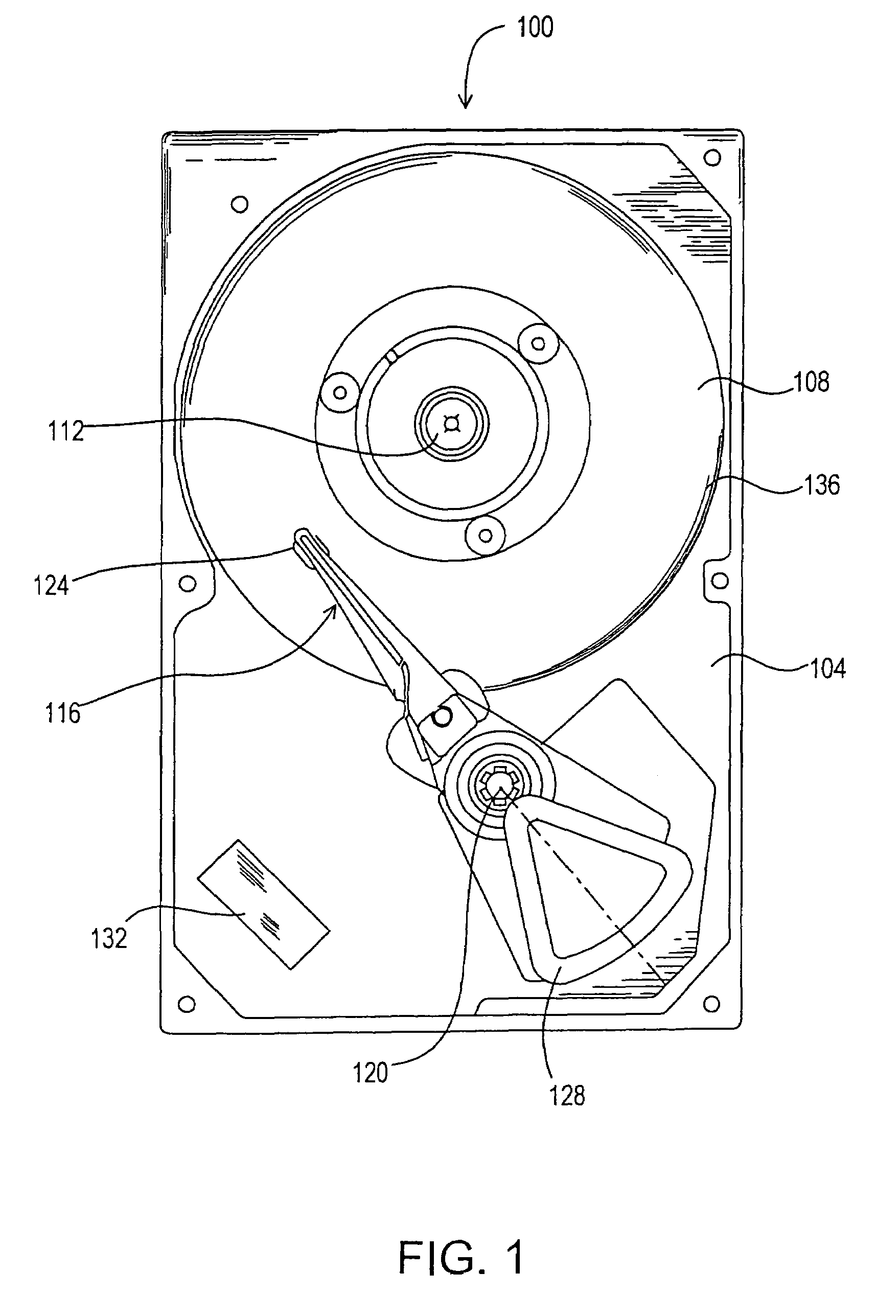
[0032]FIG. 1 illustrates a disk drive 100 that includes a base 104 and a magnetic disk (or disks) 108 (only one of which is shown). The disk 108 is interconnected to the base 104 by a spindle motor (not shown) mounted within or beneath the hub 112 such that the disk 108 can be rotated relative to the base 104. An actuator arm assembly 116 is interconnected to the base 104 by a bearing 120 and suspends a transducer head 124 at a first end. The transducer head 124 reads data from and writes data to the disk 108. A voice coil motor 128 pivots the actuator arm assembly 116 about the bearing 120 to radially position the transducer head 124 with respect to the disk 108. The voice coil motor 128 is operated by a controller 132 that is operatively connected to a host computer (not shown). By changing the radial position of the transducer head 124 with respect to the disk 108, the transducer head 124 can access different tracks 136 on the disk 108.

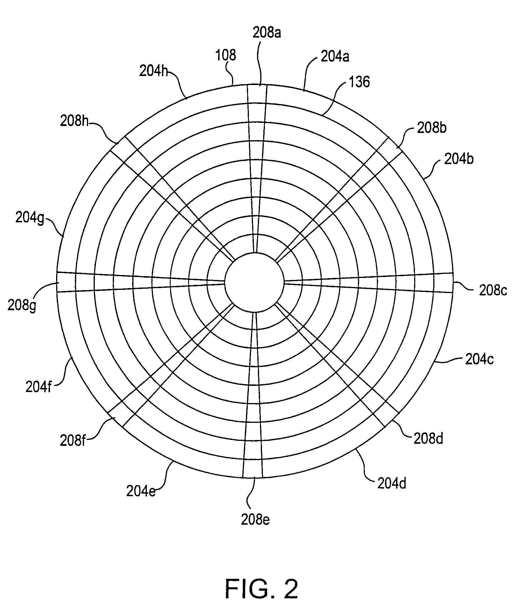
[0033]FIG. 2 illustrates the disk 108 in mor...


PUM

PropertyMeasurementUnit
widthaaaaaaaaaa
shock thresholdaaaaaaaaaa

Abstract

Dynamically detecting off-track errors in a disk drive by adjusting transducer head position control parameters in response to shock events. In an embodiment, shock events with large magnitude trigger a severe shock timer which lengthens the write fault before write operations resume. In another embodiment, a lower shock threshold is used following an initial shock event. In yet another embodiment, a lower shock threshold is used if an accumulated average position error of the transducer head is large.

Description

CROSS-REFERENCE TO RELATED APPLICATION[0001]This application is a divisional of U.S. application Ser. No. 09 / 639,567 filed Aug. 15, 2000 now U.S. Pat. No. 6,882,489 which is incorporated by reference in its entirety.FIELD OF THE INVENTION[0002]The present invention relates to positioning and control of disk drive transducer heads. In particular, the present invention relates to protecting against track misregistration errors when the transducer head is off-track.BACKGROUND OF THE INVENTION[0003]Disk drives store information on magnetic disks. Typically, the information is stored in concentric data tracks on the disks. The tracks are usually divided into sectors. Information is written to and read from the disk by a transducer head. The transducer head may include a read head separate from a write head, or the read and write heads may be integrated. The transducer head is mounted on an actuator arm assembly that moves the transducer head radially over the disk. Accordingly, the movem...

Claims


Application Information

Patent Timeline
Patent Type & Authority Patents(United States)
IPC IPC(8): G11B19/04
CPCG11B5/5582G11B19/04G11B19/06
Inventor BRUNNETT, DONPURKETT, JOHNLIIKANEN, BRUCE
Owner MAXTOR
Why Eureka
Try Eureka