Stator compound having an nbir terpolymer elastomeric base and stators and downhole motors using the same

a technology of nbir terpolymer and elastomeric base, which is applied in the field of stator compound having nbir terpolymer elastomeric base and stators and downhole motors using the same, can solve the problems of high swell, poor dynamic performance of stator liners, and inability to formulate a high-performance stator compound for fabricating stator liners, etc., to achieve enhanced dynamic mechanical properties, improved swell properties in diesel

a technology of nbir terpolymer and elastomeric base, which is applied in the field of stator compound having nbir terpolymer elastomeric base and stators and downhole motors using the same, can solve the problems of high swell, poor dynamic performance of stator liners, and inability to formulate a high-performance stator compound for fabricating stator liners, etc., to achieve enhanced dynamic mechanical properties, improved swell properties in diesel

US20160362543A1Active Publication Date: 2016-12-15ABACO DRILLING TECH LLC

Image

  • Stator compound having an nbir terpolymer elastomeric base and stators and downhole motors using the same
  • Stator compound having an nbir terpolymer elastomeric base and stators and downhole motors using the same
  • Stator compound having an nbir terpolymer elastomeric base and stators and downhole motors using the same

Examples


Embodiment Construction

[0015]The principles of the present invention and their advantages are best understood by referring to the illustrated embodiment depicted in FIGS. 1-2 of the drawings, in which like numbers designate like parts.

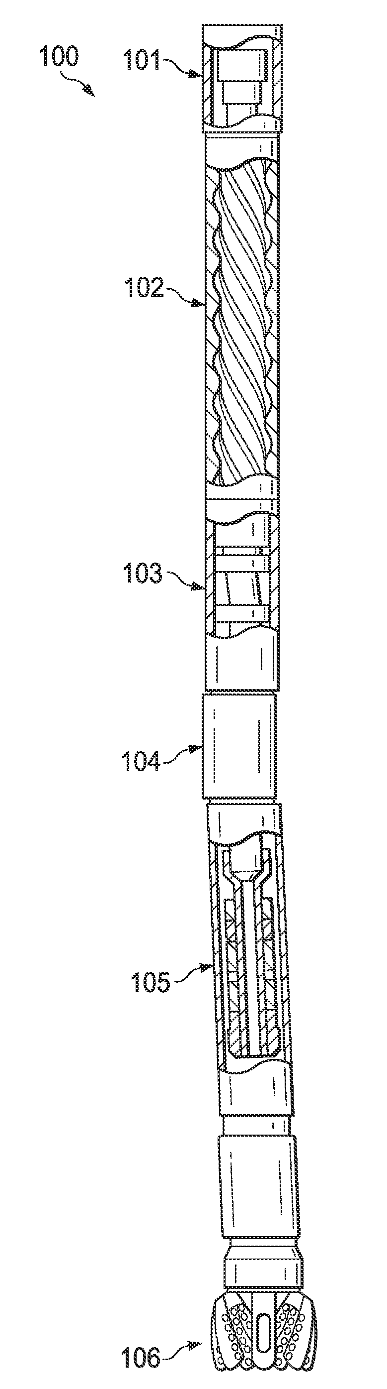
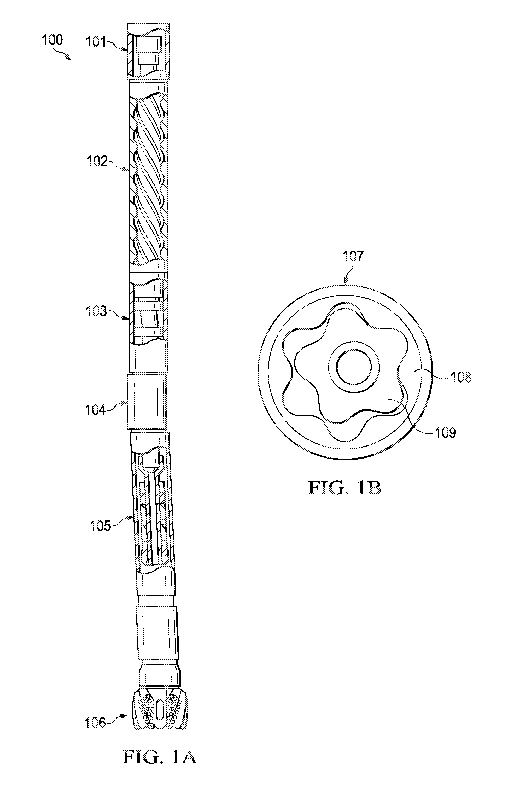
[0016]FIG. 1A is a diagram of an exemplary downhole motor assembly 100, which attaches to the end of a drilling string during oil and gas drilling operations. Exemplary downhole motor assembly 100 includes a top sub 101, stator and rotor assembly 102, transmission 103, offset or adjustable housing 104, bearing assembly 105, and drill bit 106. FIG. 1B is an end cut-away view of stator and rotor assembly 102 and shows the helical rotor 109 offset within the helical liner 108 of stator tube 107.

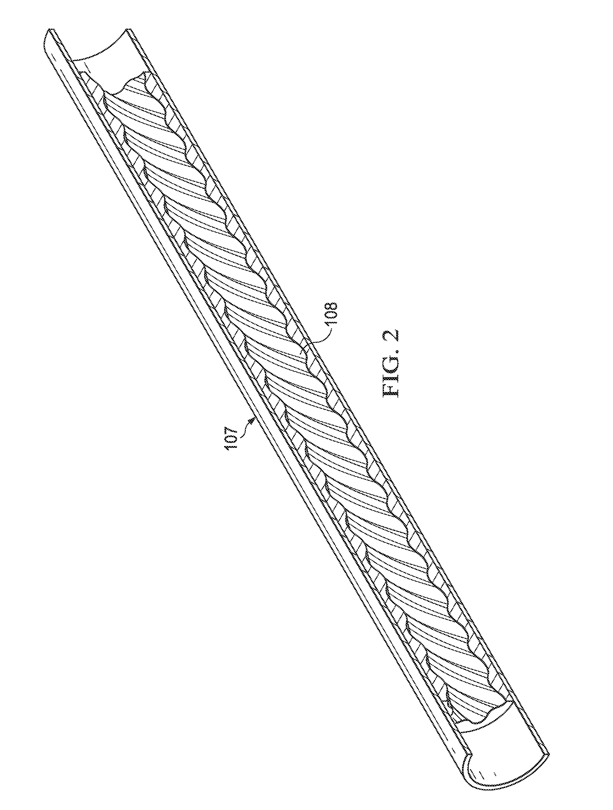
[0017]FIG. 2 is a side cutaway view of stator and rotor assembly 102 of FIG. 1, which shows stator tube 107 and associated molded stator elastomer lining 106 in further detail. The fabrication of molded stator elastomer lining 108 is one exemplary use of a NBIR terpolymer embodying the p...


PUM

PropertyMeasurementUnit
tensile strengthaaaaaaaaaa
elongationaaaaaaaaaa

Abstract

A stator compound including an acrylonitrile butadiene isoprene rubber (NBIR) terpolymer elastomeric base.

Description

CROSS-REFERENCE TO RELATED APPLICATION[0001]The present application claims the benefit of U.S. Provisional Application Ser. No. 62 / 175,854, filed Jun. 15, 2015, which is incorporated herein by reference for all purposes.FIELD OF INVENTION[0002]The present invention relates in general to oil and gas drilling equipment, and in particular to a stator compound having NBIR terpolymer elastomeric base and stators and downhole motors using the same.BACKGROUND OF INVENTION[0003]In oil and gas drilling industry, the downhole motor (“mud motor”) is normally disposed between the end of the drill string and the drill bit. When drilling mud is pumped down the drill string from the surface, the mud motor rotates the drill bit allowing it to cut through the surrounding material. Downhole motors are particularly useful in directional drilling, which requires steering the drill bit in a desired direction.[0004]A typical downhole motor includes a rotating shaft (“rotor”) disposed within a fixed housi...

Claims


Application Information

Patent Timeline
15 Dec 2016
Publication
US20160362543A1
IPC
C08L9/02
CPC
C08L9/02
Inventors
KYKER, GARY STEPHEN