Flash boiling apparatus

Active Publication Date: 2020-01-09
TETRA LAVAL HLDG & FINANCE SA
View PDF0 Cites 0 Cited by
  • Summary
  • Abstract
  • Description
  • Claims
  • Application Information

AI Technical Summary

Benefits of technology

[0008]It is an object of the invention to at least partly overcome one or more of the above-identified limitations of the prior art. In particular, it is an obj

Problems solved by technology

This impingement and/or flow may cause excessive wear of the vacuum vessel, in particular if the liquid food product comprises parti

Method used


Image

  • Flash boiling apparatus
  • Flash boiling apparatus
  • Flash boiling apparatus

Examples


Embodiment Construction

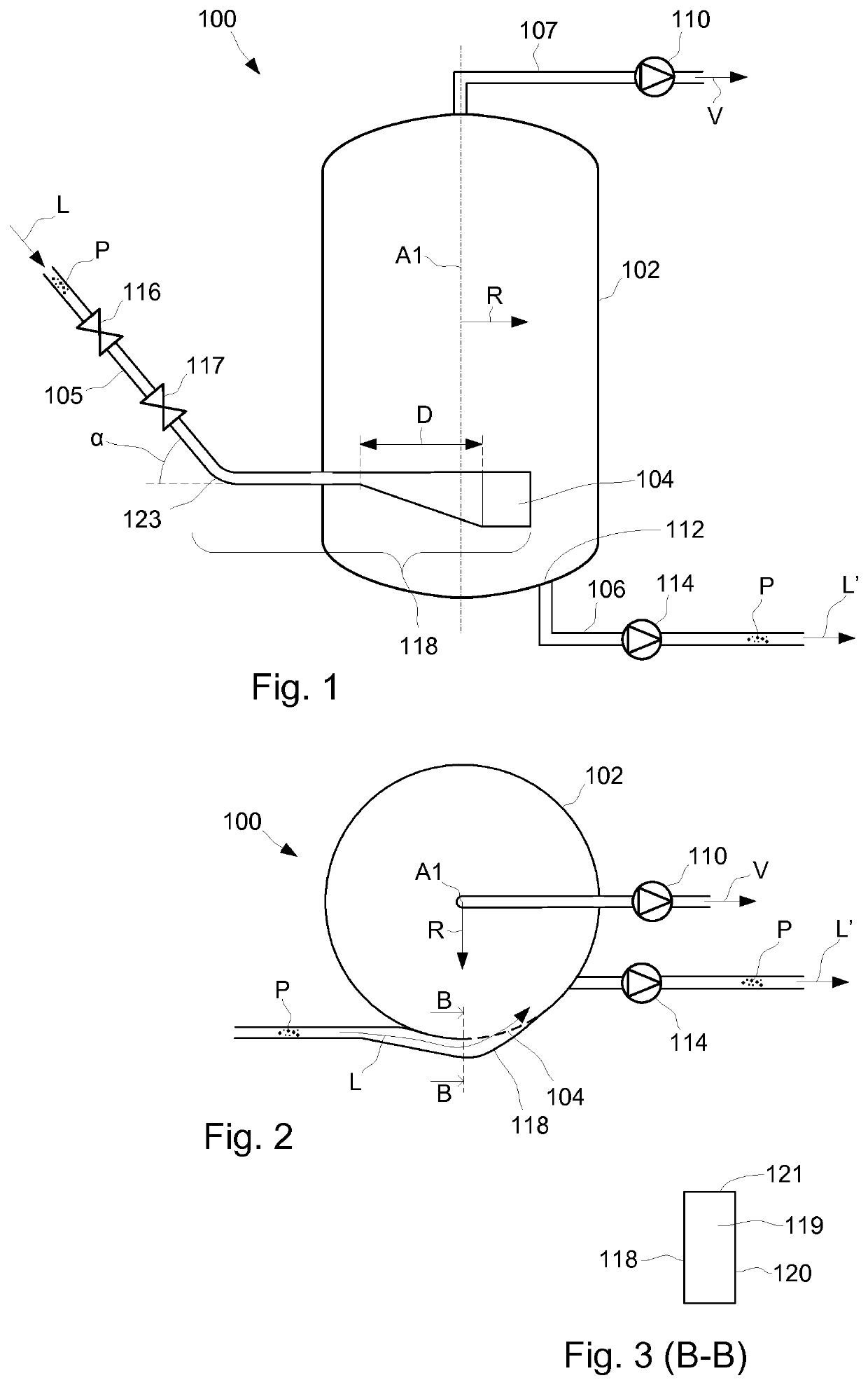
[0021]With reference to FIGS. 1 and 2 an example of a flash boiling apparatus 100 is schematically illustrated. The flash boiling apparatus 100 comprises a vacuum vessel 102, a product inlet pipe 105, a product outlet pipe 106 and a vapour outlet pipe 107. The vacuum vessel 102 has a cylindrical shape that extends along a central cylinder axis A1. A direction R that is perpendicular to the cylinder axis A1 defines a radial direction of the vacuum vessel 102.

[0022]The product inlet pipe 105 supplies a liquid food product L that comprises particles P into the vacuum vessel 102 via a product inlet 104 of the vacuum vessel 102. A vacuum pump 110 is arranged in the vapour outlet pipe 107 for providing a low pressure in the vacuum vessel 102. The pressure in the product inlet pipe 105 is higher than the pressure in the vacuum vessel 102, such that flash boiling may occur when the liquid food product L enters the vacuum vessel 102.

[0023]The liquid food product L may be a diary based produc...


PUM


Abstract

A flash boiling apparatus for a liquid food product that includes particles, the apparatus including a vacuum vessel provided with a product inlet and a product outlet for liquid food product, a pressure relief valve arranged upstream the product inlet for providing a pressure drop that results in flash boiling of the liquid food product, and an inlet section arranged between the pressure relief valve and the product inlet, for conveying the liquid food product from the pressure relief valve to the product inlet. The inlet section includes a through-flow area that increases in a direction from the pressure relief valve to the product inlet, such that a flow velocity of the liquid food product decreases when it passes the inlet section.

Description

TECHNICAL FIELD[0001]The present application relates to a flash boiling apparatus for liquid food products that comprises particles, a food processing system comprising the flash boiling apparatus, and a method for flash boiling liquid food products that comprises particles.BACKGROUND ART[0002]Today, in many liquid food processing systems a flash boiling stage may be included for a number of reasons. For example, when heat treating a liquid food product by steam injection for killing microorganisms, the product is held at a heat treatment temperature for a few seconds before it is introduced into a vacuum vessel to be flash boiled, or flash cooled. The flash boiling reduces the temperature of the product and removes an amount of vapour that equals the amount of steam that was injected for the heat treatment.[0003]Flash boiling may also be used when it is desired to increase the concentration of a liquid food product. The product is then introduced in a vacuum vessel that acts as an ...

Claims


Application Information

Patent Timeline
IPC IPC(8): A23L3/18B01D3/06A23L3/00C02F1/06
CPCC02F1/06A23L3/18A23L3/001A23V2002/00B01D3/06A61L2/07B01D19/0036B01D1/0064A23L3/16A23L3/015A47J31/00A23C3/037A23L3/22
Inventor SKOGLUND, TOMASINNINGS, FREDRIKERIXON, MARTINNILSSON, SANDRA
Owner TETRA LAVAL HLDG & FINANCE SA
Why Eureka
Try Eureka