Brush device having a litz wire for an electric machine

a brush device and electric machine technology, applied in the direction of current collectors, dynamo-electric machines, supports/encloses/casings, etc., can solve the problems of limited wear length, brush is pressed against the commutator, and the commutator is subject to wear during operation, so as to improve the service life, the effect of increasing the number of operations and prolonging the running tim

a brush device and electric machine technology, applied in the direction of current collectors, dynamo-electric machines, supports/encloses/casings, etc., can solve the problems of limited wear length, brush is pressed against the commutator, and the commutator is subject to wear during operation, so as to improve the service life, the effect of increasing the number of operations and prolonging the running tim

US20120025666A1Inactive Publication Date: 2012-02-02ROBERT BOSCH GMBH

Image

  • Brush device having a litz wire for an electric machine
  • Brush device having a litz wire for an electric machine

Examples


Embodiment Construction

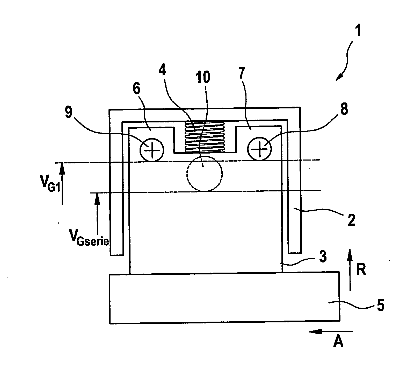
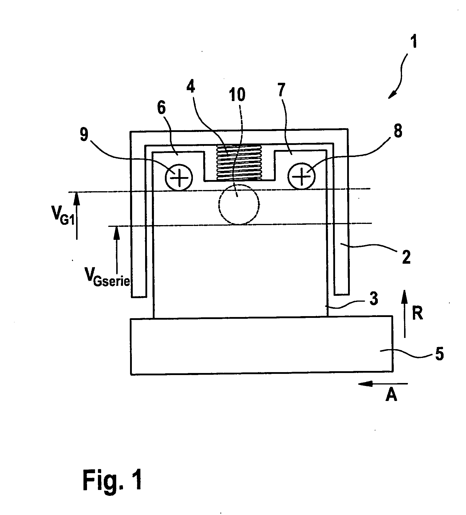
[0023]In a schematic side view, FIG. 1 shows a brush device 1, according to the exemplary embodiments and / or exemplary methods of the present invention, having a brush support 2, in which a brush 3 is accommodated. Brush 3 is prestressed against commutator 5 using a spring 4, and is pressed against it. In radial direction R, brush 3 has brush starts 6, 7, situated in parallel to spring 4, which are situated in the direction of axis A in front of and behind spring 4. According to a production method according to the present invention, in brush starts 6, 7, at least two litz wires, a first litz wire 8 and a second litz wire 9 are press-fit with brush 3. The first and second litz wires 8, 9 have a smaller cross section than a single litz wire 10 according to the related art, which is situated in the radial direction serially under spring 4 in brush 3. Litz wire 10 is drawn in as a dotted line, since it represents the related art, and not the exemplary embodiment according to the presen...


PUM


Abstract

A brush device for an electric machine is described, having a brush mount that has a brush which is accommodated in it and having a first integrated litz wire, having a first spring, which prestresses the brush against a commutator. In order to create an E machine having an improved service life, at least one second litz wire is developed integrated into the brush.

Description

FIELD OF THE INVENTION [0001]The present invention relates to a brush device for an electric machine having a brush mount, and having a brush accommodated in the brush mount, into which a first litz wire is integrated, and having a spring which prestresses the brush in the brush mount against a commutator.BACKGROUND INFORMATION [0002]It is understood that there are mechanically commutated electric machines (E machines) that have in each case one litz wire integrated in the brush. Mechanically commutated DC current motors are used to start internal combustion engines. The current is introduced into the armature winding via the commutator via one or more pair(s) of brushes. In most cases these brushes are made of a sintered material, which predominantly includes copper and graphite components. Because of their high proportion of graphite, the brushes are also called carbon brushes. These brushes as well as the commutator are subject to wear during operation.[0003]The DC motor, which i...

Claims


Application Information

Patent Timeline
02 Feb 2012
Publication
US20120025666A1
IPC
H01R39/36; H01R39/415
CPC
H01R39/36; H02K5/148; H01R39/40
Inventors
BAYER, MICHAEL