
Foot cushioning construct and system for use in an article of footwear

a technology of foot cushioning and construction, applied in the field of footwear articles, can solve the problems of reducing the comfort of wearers,

Inactive Publication Date: 2007-08-14
CREATIVE PROD SOLUTIONS
View PDF15 Cites 51 Cited by
  • Summary
  • Abstract
  • Description
  • Claims
  • Application Information

AI Technical Summary

Benefits of technology

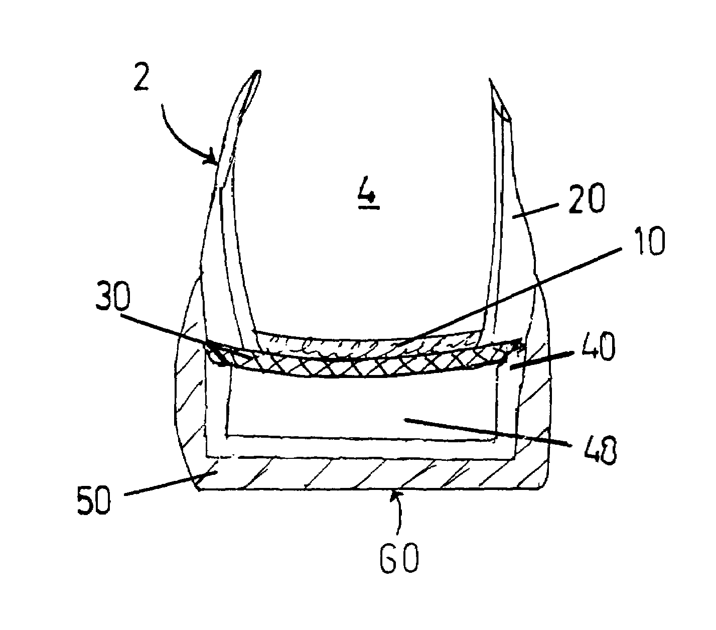
[0017]an elastic stretchsole which is joined to the perimeter edge of and forms an elastic end closure for the shoe upper, said joined elastic stretchsole being able to deform and rebound repeatedly on-demand in response to the compression forces generated thereon by a person's foot, and
[0018]at least one median cavity housed within the outsole of the footwear article and positioned adjacent to said joined elastic stretchsole of the shoe upper, said median cavity means presenting not less than one pre-positioned volume able to receive at least a part of a deformed elastic stretchsole and cushion the compression forces generated thereon by a person's foot.
[0021]at least one preformed cavity chamber of determinable dimensions and configuration housed within the outsole of the footwear article, said preformed cavity chamber being positioned adjacent to said joined elastic stretchsole of the shoe upper and presenting not less than one median cavity able to receive at least a part of a deformed elastic stretchsole and cushion the compression forces generated thereon by a person's foot.

Problems solved by technology

These compressible padding materials, however, present multiple problems.
First, these materials are relatively inefficient in their ability to absorb shock and cushion the foot.
Second, the materials typically become compacted after repeated use and often lose their cushioning properties.
Third, with severe foot impact uses, these designs allow a full compression of the material and “bottom out” quickly, thereby transmitting the severe impact forces to the wearer's foot and body.
In addition, when made thicker to avoid this third problem, these materials often become unstable, can become cumbersome and heavy, and typically interfere with the foot in performance of the exercise or physical routine.
The flaw in all of these conventionally available technologies and footwear designs is that each of these modifications concern themselves solely with the conventional outsole of the shoe to compress more efficiently; but none of these design modifications allow the upper of the shoe to assist in either a deceleration of the compression forces and shock upon the foot or in a cushioning the foot itself.
Thus, the conventional footwear constructions are dedicated completely to materials and designs intended for compression within the outsole / midsole of the shoe; and none of the conventional footwear constructions allow the person's foot to either move or decelerate within the upper of the shoe in order to cushion the foot and to absorb the impact shock.

Method used


Image

  • Foot cushioning construct and system for use in an article of footwear
  • Foot cushioning construct and system for use in an article of footwear
  • Foot cushioning construct and system for use in an article of footwear

Examples


second alternative embodiment

A SECOND ALTERNATIVE EMBODIMENT

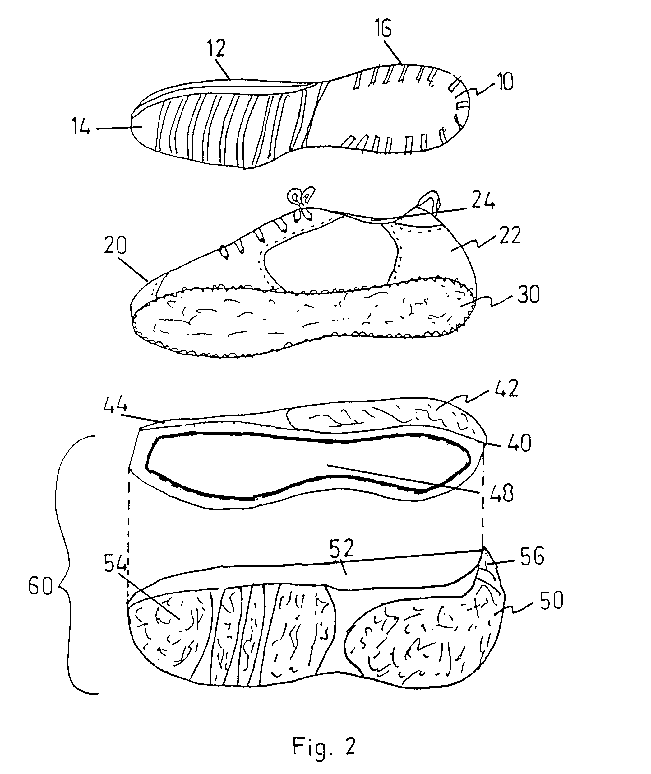
[0113]A second alternative format for the present invention is illustrated by FIGS. 18 and 19 respectively. The essential component parts of the footwear construction are very similar to the preferred embodiment previously described herein and illustrated by FIGS. 1–11 respectively. This second alternative embodiment and construction, however, presents two unusual and valuable differences: First, there is a meaningful change in median cavity zone 40 of outsole unit 60 in that the preformed and pre-positioned median cavity 48 now occupies only a limited portion of the overall dimensions and total volume presented by outsole unit 60 as a whole. Second, there is a major alteration and modification to insole 10 employed within fully assembled shoe 2 These substantive differences are illustrated in detail by FIG. 18.

[0114]As shown by the exploded view of FIG. 18, modified insole 410 comprises top surface 412, bottom surface 414 and perimeter edge 416. In ad...

third alternative embodiment

A THIRD ALTERNATIVE EMBODIMENT

[0123]A third alternative embodiment of the present invention providing a foot cushioning construct and a shock absorbing system is illustrated by FIG. 20 as a transverse cross-sectional view of the heel area in an assembled shoe. This third alternative embodiment typically employs insole 10, upper assembly 20 including stretchsole 30, a traditionally known midsole 640, and a conventional outsole 660. In this alternative embodiment, stretchsole 30 is as previously described herein; and forms a discrete elastic end closure for upper assembly 20. Stretchsole 30 is thus the unique and essential element which acts in concert with traditional midsole 640 and conventional outsole 660 in this construction.

[0124]In this embodiment and construction, a commonly known capsule 648 lies positioned within the substance of traditional midsole 640 as the means for foot cushioning; and both traditional midsole 640 and capsule 648 are housed and contained by conventional...


PUM


Abstract

The present invention provides an unique improvement in foot cushioning constructs and shock absorbing systems for a constructed article of footwear to be worn by a person. The invention employs a deformable and re-formable elastic stretchsole joined as a planar sheet to the perimeter edge of the shoe upper and forms an elastic end closure for the shoe upper; and includes not less than one pre-positioned median cavity able to receive at least a part of the deformed elastic stretchsole layer and cushion the compression forces generated thereon by a person's foot. The foot cushioning construct and system provides a trampoline effect that will lessen the impact on the foot and create greater comfort for the wearer of the shoe.

Description

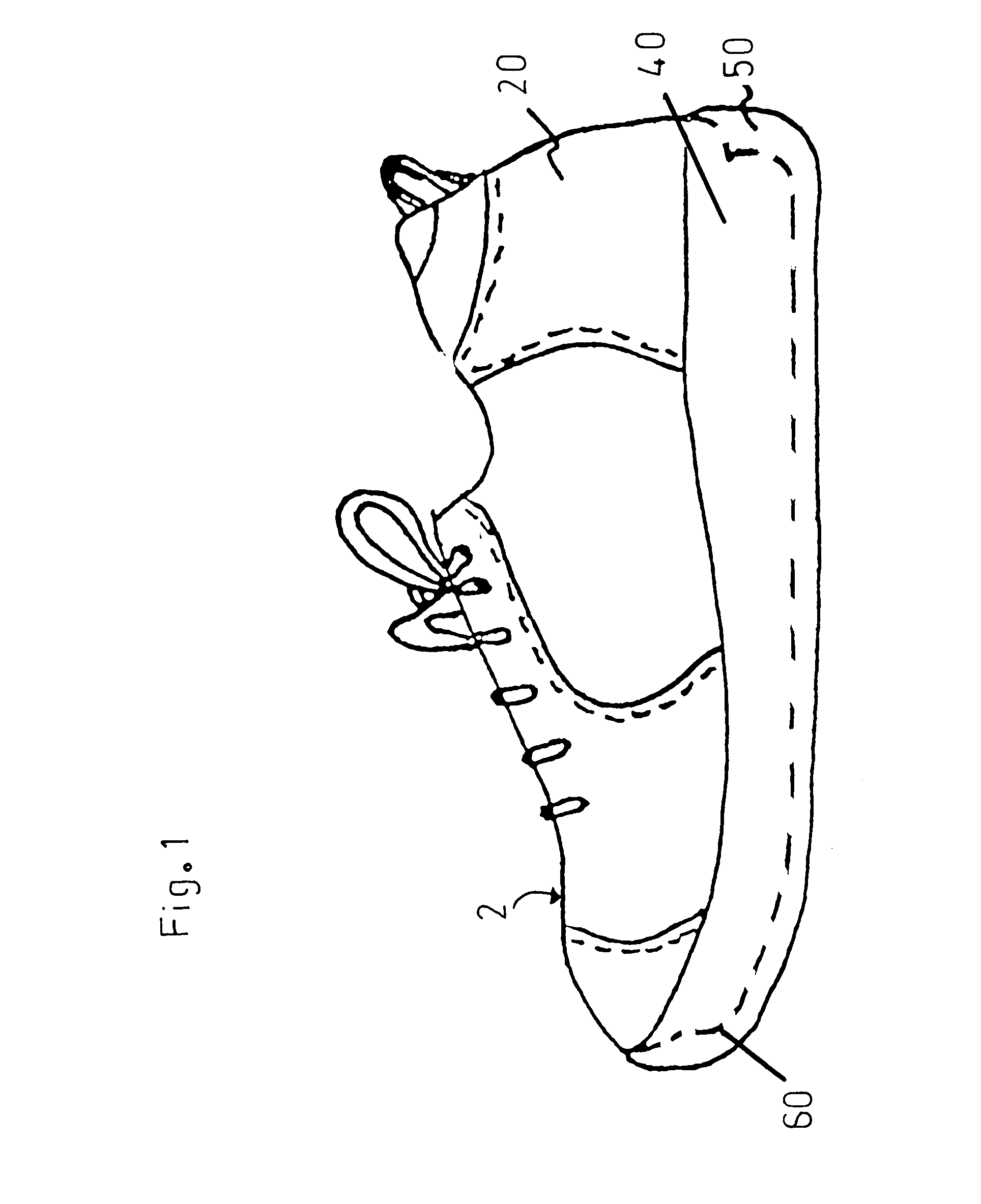
FIELD OF THE INVENTION[0001]The present invention is concerned with articles of footwear such as athletic and walking shoes; and is particularly directed to means for foot cushioning and shock absorption to control the compression forces generated by a person when standing, walking, or running.BACKGROUND OF THE INVENTION[0002]A conventional shoe made today typically has three major components, as follows.[0003](1) The upper: This component entity is an assembly which holds and conforms to the shape of the person's foot. The traditional purpose of the shoe upper is to fit the foot properly, comfortably, and snuggly. Ideally, this upper portion of the shoe will also be aesthetically pleasing, be comfortable, and be highly durable.[0004](2) The Outsole: This component entity is the lower exterior and bottom component of the shoe; and is typically joined to the exterior surface of the shoe upper directly using adhesives or other bonding techniques. The outsole typically is constructed o...

Claims


Application Information

Patent Timeline
Patent Type & Authority Patents(United States)
IPC IPC(8): A43B13/18A43B13/20A43B7/06A43B9/00A43B9/02A43B13/38
CPCA43B7/06A43B7/144A43B7/1445A43B9/00A43B9/02A43B13/20A43B13/383
Inventor MORRIS, KWAMESALEM, MARTIN
Owner CREATIVE PROD SOLUTIONS
Learn More