Insert for heat exchanger tube

a technology of inserts and heat exchangers, which is applied in the direction of stationary plate conduit assemblies, lighting and heating apparatuses, laminated elements, etc., and can solve the problems of heat exchangers, high material wastage, and inability to meet the needs of users

Inactive Publication Date: 2007-08-14
MODINE MFG CO
View PDF11 Cites 25 Cited by
  • Summary
  • Abstract
  • Description
  • Claims
  • Application Information

AI Technical Summary

Benefits of technology

[0018]In yet another aspect of the present invention, a method of producing an insert according to the still another aspect of the invention is provided, including (a) transporting a sheet metal strip at a specific feed rate and specific advance through a deformation die on an eccentric press that operates with continuous stroke operation, and (b) selectively changing one of the feed rate and continuous stroke speed. At a constant continuous stroke speed, the feed rate when reduced forms the first section and the feed rate when increased forms the second section, and at a constant continuous feed rate, the continuous stroke speed when reduced forms the second section and the continuous stroke speed when increased forms the second section.

Problems solved by technology

However, it is necessary that such inserts be punched out with the corresponding slope angle, so that higher material wastage could possibly occur.
Since this is not willingly accepted, in terms of achieving the optimal ratio of cooling performance to pressure loss, relatively large bypasses are often left between the edges of the heat exchanger tube and the edges of the insert.
However, such bypasses effect the overall flow characteristics of the heat exchanger and they are therefore often not desirable.
However, the advantages of heat exchange provided by fluid flow through multiple wavelengths (through flank openings) are also not received.

Method used


Image

  • Insert for heat exchanger tube
  • Insert for heat exchanger tube
  • Insert for heat exchanger tube

Examples


Embodiment Construction

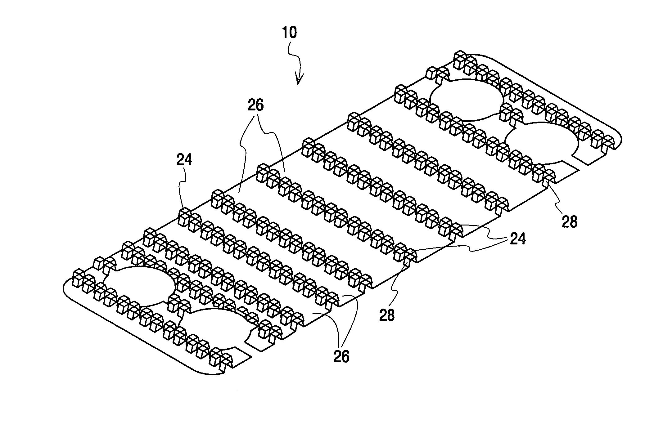
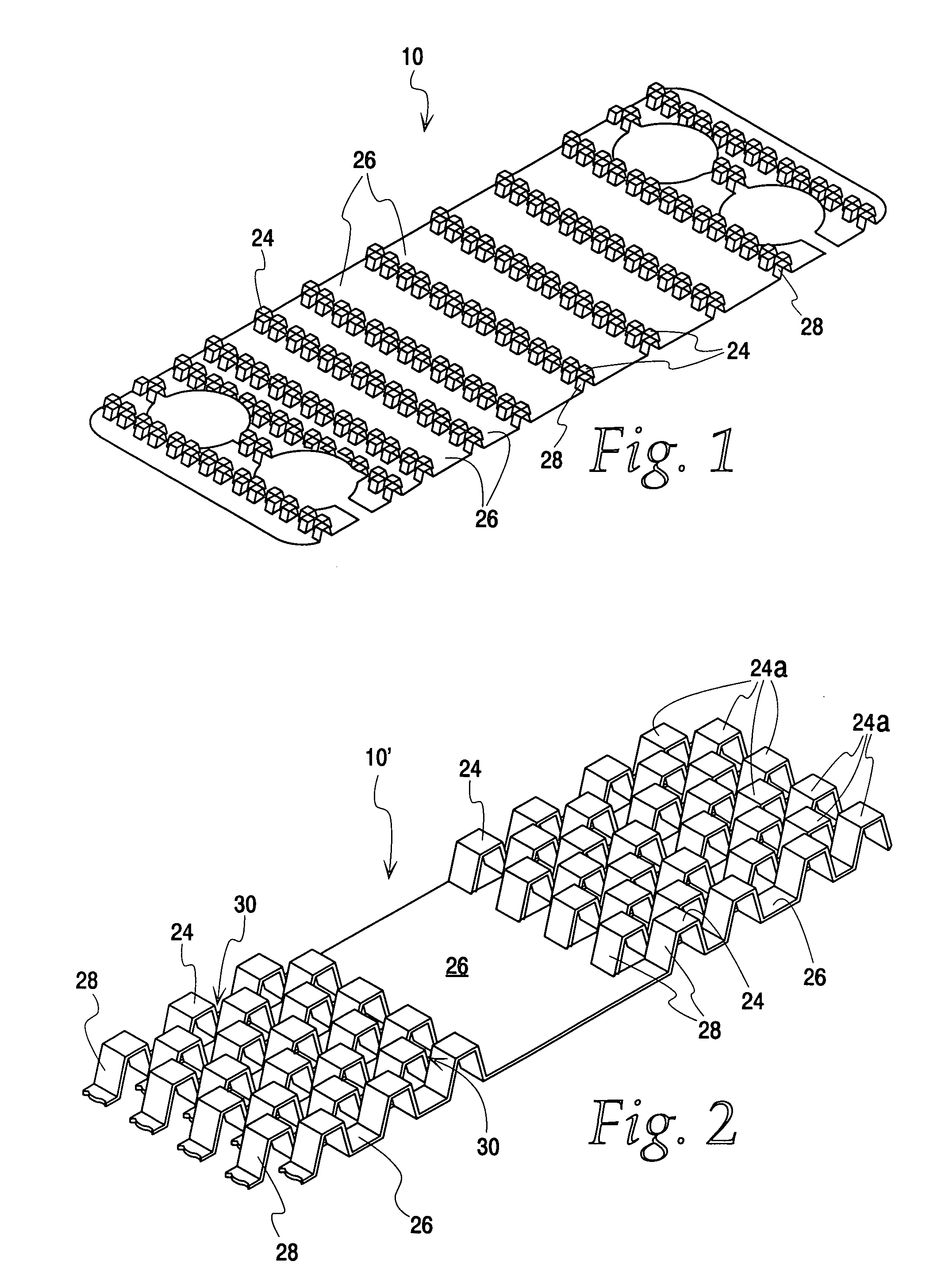
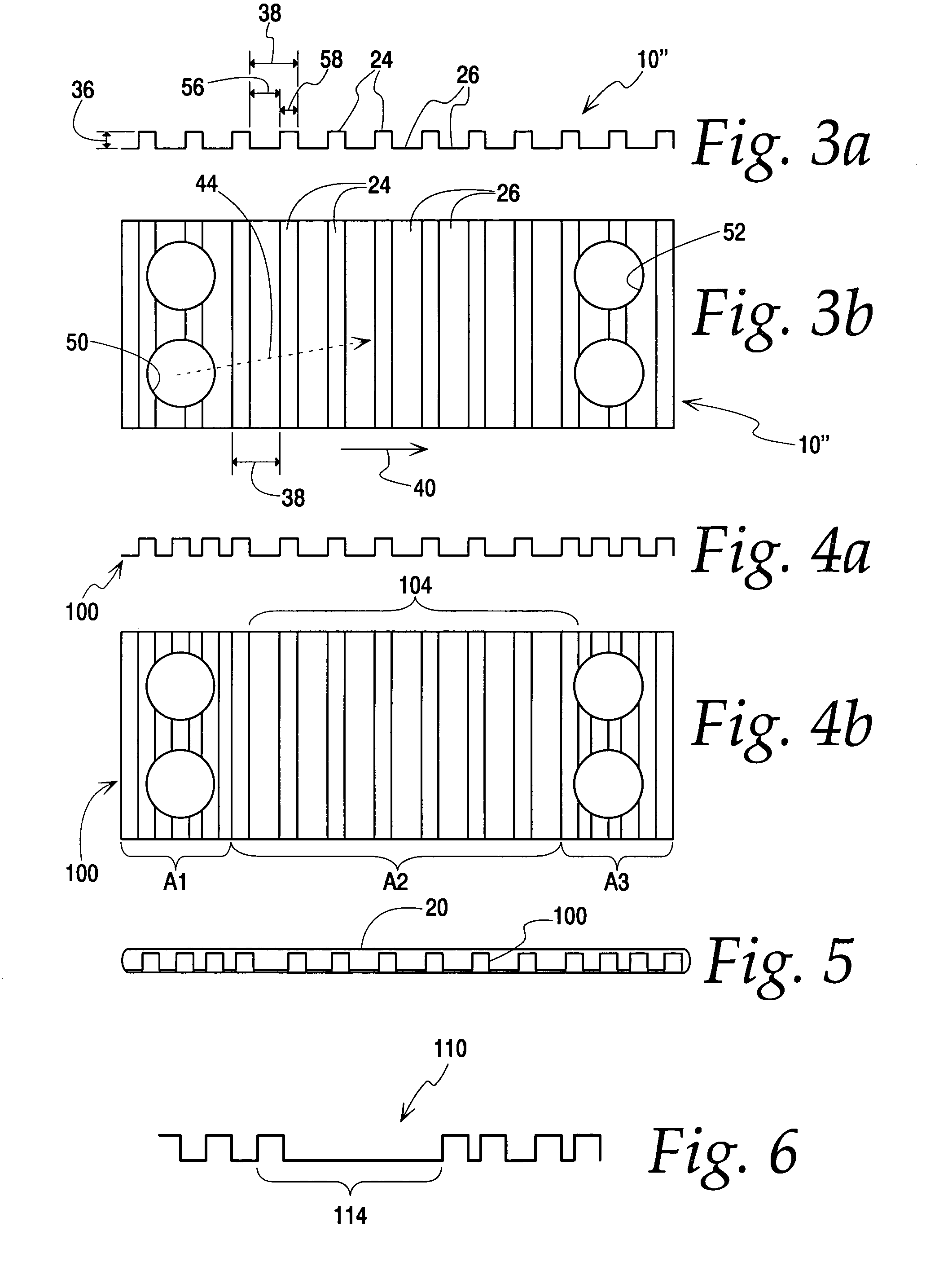
[0026]The present invention concerns a corrugated insert 10 which may be inserted into a heat exchanger tube 20 (see FIG. 5).

[0027]It should be understood that the present invention could be advantageously used in connection with many different heat exchanger configurations. Thus, the heat exchanger tube with which inserts according to the present invention may be used may be arbitrarily designed according to the requirements of the heat exchanger, with the inserts 10 designed in accordance with the tube design. For example, the heat exchanger tube 20 may be a welded, soldered or drawn flat tube, as may be used, for example, in air-cooled charge air coolers.

[0028]For illustration purposes herein, the present invention is described with reference to practical examples which refer to the insert in a heat exchanger tube of an oil-cooler such as shown, for example in European Patent EP 742 418 B1, the full disclosure of which is hereby incorporated by reference. Particularly, reference ...


PUM

PropertyMeasurementUnit
wavelengthaaaaaaaaaa
wavelengthsaaaaaaaaaa
pressure dropaaaaaaaaaa

Abstract

An insert adapted to connect to opposite walls in a heat exchanger tube, including a corrugated sheet having alternating wave crests and wave troughs connected by wave flanks having openings therein, wherein at least some of the wave crests have a length different than the length of the wave troughs, and/or adjacent sections have different wavelength waves. Such inserts may be produced by transporting material sheets through a press, where the sheet feed rate and/or the press stroke speed may be selectively varied.

Description

CROSS REFERENCE TO RELATED APPLICATION(S)[0001]Not applicable.STATEMENT REGARDING FEDERALLY SPONSORED RESEARCH OR DEVELOPMENT[0002]Not applicable.REFERENCE TO A MICROFICHE APPENDIX[0003]Not applicable.TECHNICAL FIELD[0004]The present invention is directed toward inserts for corrugated heat exchanger tubes, and particularly toward turbulators and methods of producing same.BACKGROUND OF THE INVENTION AND TECHNICAL PROBLEMS POSED BY THE PRIOR ART[0005]Heat exchangers typically provide separate flow paths for different media, with heat being exchanged between the media through the materials separating the flow paths. For example, in radiators, a plurality of tubes are commonly provided for carrying heated fluid, with air blown over the tubes (and fins attached to the tubes) so that heat from the fluid is dissipated through the tube walls (and attached fins) to the air, thereby cooling the fluid.[0006]It is important that the flow paths in such heat exchangers facilitate such heat exchan...

Claims


Application Information

Patent Timeline
Patent Type & Authority Patents(United States)
IPC IPC(8): F28F1/40F28F13/08F28F13/12B21D13/02B21D53/04F28D9/00F28F3/02
CPCB21D13/02B21D53/04F28D9/005F28F3/025F28F2215/04Y10S165/916
Inventor SAGASSER, ROB J.BLUTLING, JENSKASINGER, RAINER
Owner MODINE MFG CO
Why Eureka
Try Eureka