
System for detecting the status of a vent associated with a fluid supply upstream of an infusion pump

a technology for infusion pumps and fluid supply, which is applied in the direction of positive displacement liquid engines, process and machine control, instruments, etc., can solve the problems of increasing the strain on the infusion pump, reducing the flow, and inaccurately delivering the therapeutic fluid

Active Publication Date: 2007-08-14
CAREFUSION 303 INC
View PDF50 Cites 83 Cited by
  • Summary
  • Abstract
  • Description
  • Claims
  • Application Information

AI Technical Summary

Problems solved by technology

A common problem during infusion of therapeutic fluids into a patient occurs when the fluid to be infused is contained in burettes, bottles, or other non-flexible or partly flexible containers.
This negative pressure may cause a reduction in flow, leading to inaccurate delivery of the therapeutic fluid.
Where an infusion pump is used to infuse the therapeutic fluid, the negative pressure building inside the container may also increase strain on the infusion pump, and may cause the pump to sound an alarm if the desired fluid infusion rate cannot be maintained.
Another problem that can occur is that the negative pressure may result in air ingress into the system, especially at joints in the infusion line before the infusion line enters the infusion pump.
This may result in air being entrained in the therapeutic fluid, and subsequently infused into the patient.
Moreover, in cases where thin walled, yet rigid containers are used, the negative pressure may increase to such an extent that the thin walled containers collapse, possibly spilling their contents.
However, if a care-giver forgets to open the vent or the particular drug or combination of drugs being infused wets the vent, the vent will not allow passage of air, resulting in a progressively increasing negative pressure in the container and fluid line as the pump attempts to draw fluid from the container.
Moreover, such a system would be able to determine whether the intake or container-side pressure is not changing over time, indicating a stable infusion rate, or is decreasing as fluid is removed from the container, indicating lack of proper venting requiring attention by the care-giver.

Method used


Image

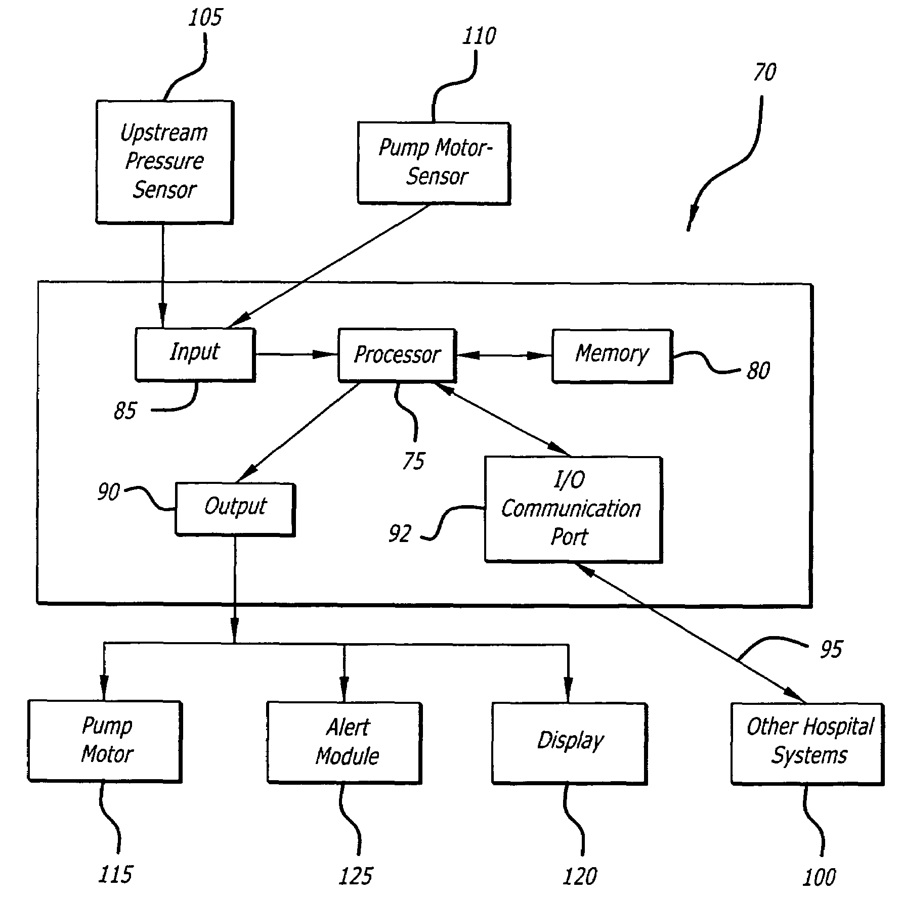
  • System for detecting the status of a vent associated with a fluid supply upstream of an infusion pump
  • System for detecting the status of a vent associated with a fluid supply upstream of an infusion pump
  • System for detecting the status of a vent associated with a fluid supply upstream of an infusion pump

Examples


Embodiment Construction

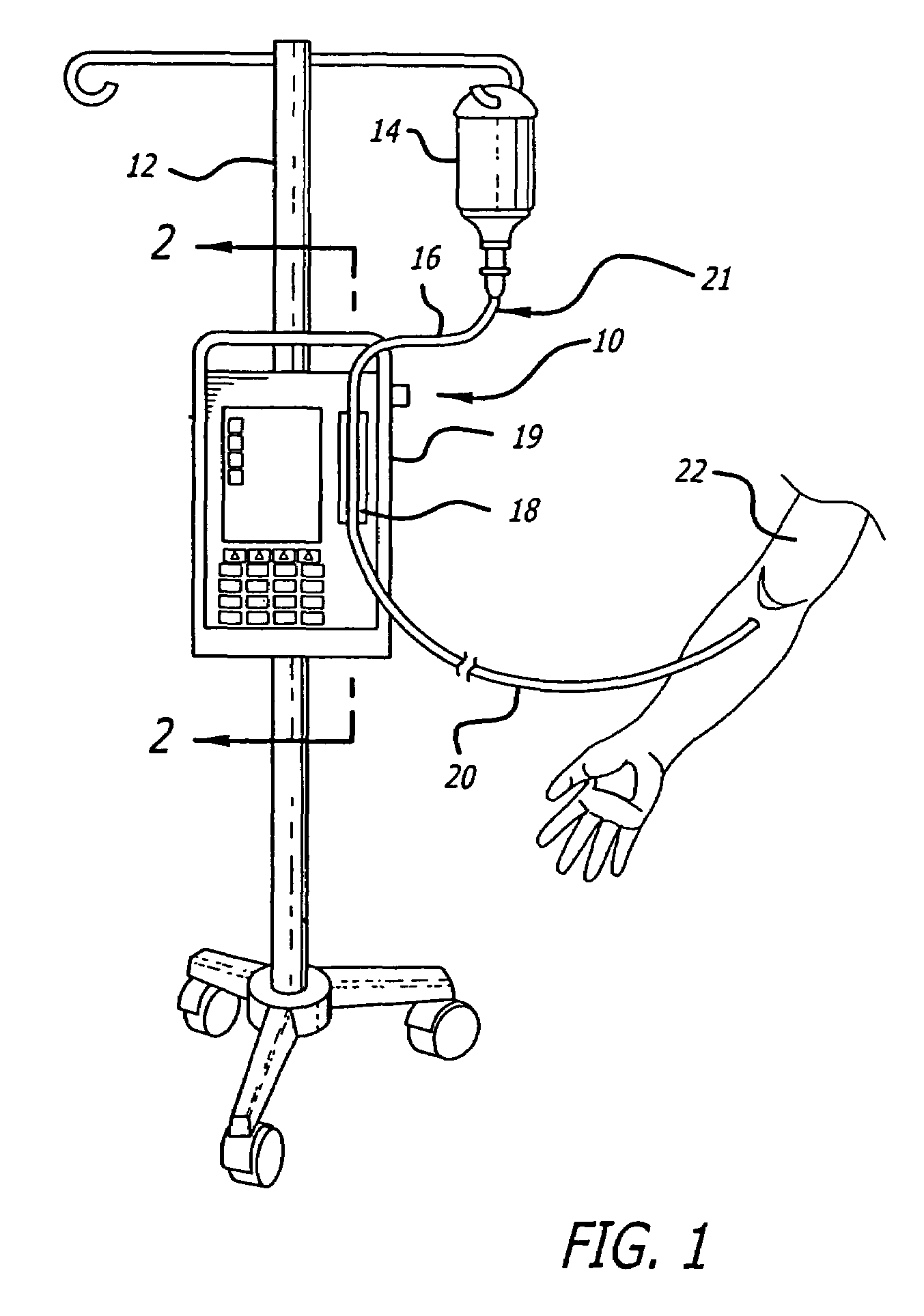
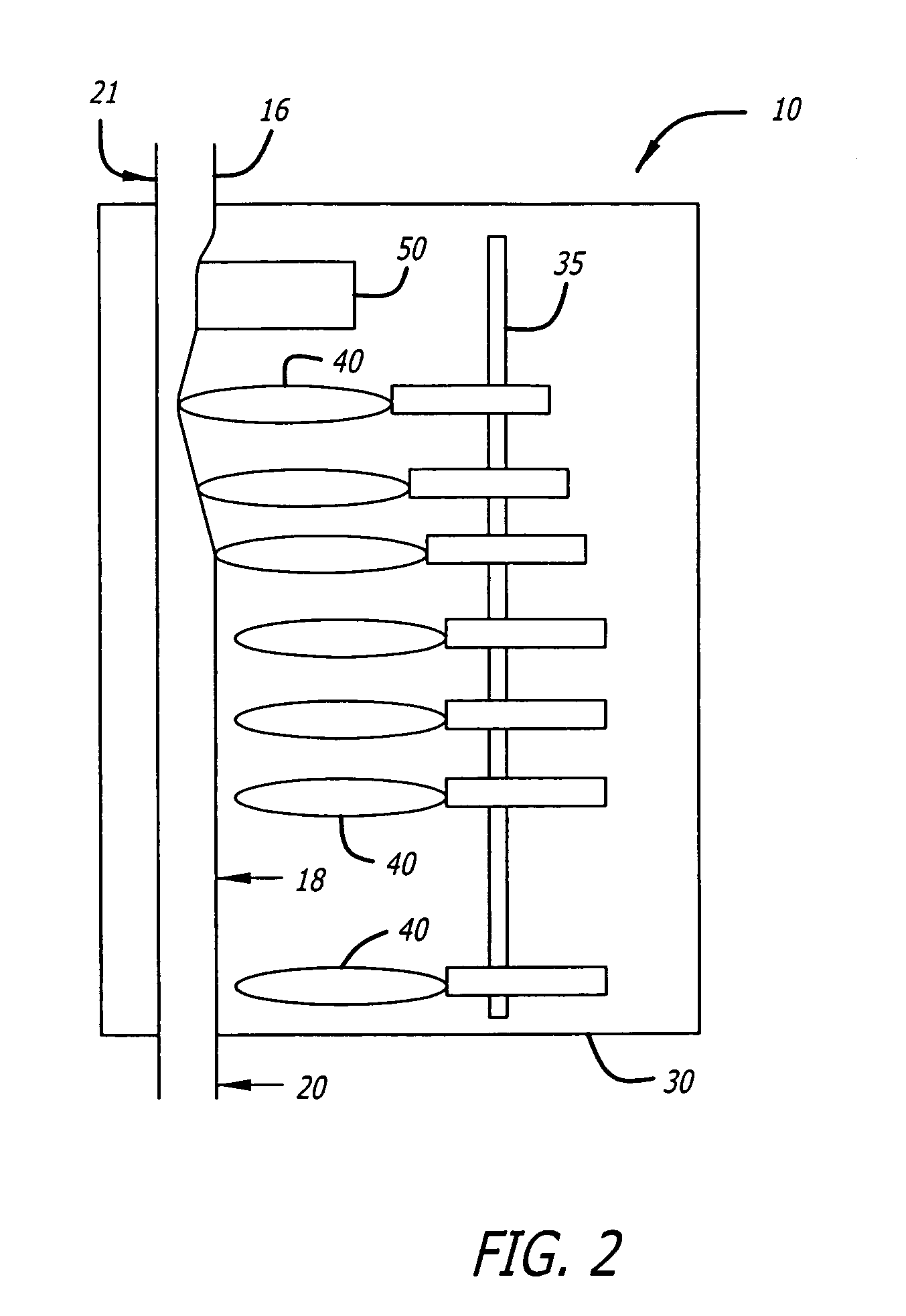
[0024]Referring now to the drawings wherein like reference numerals among the drawing represent like or corresponding elements, there is shown in FIG. 1 an infusion pump set-up, generally designated by numeral 10, shown in use in its intended environment. In particular, the infusion pump set-up 10 is shown attached to an intravenous (I.V.) pole 12 on which a fluid source 14 containing an I.V. fluid is held. The fluid source 14 is connected in fluid communication with an upstream fluid line 16. The fluid line 16 is a conventional I.V. infusion-type tube typically used in a hospital or medical environment and is made of any type of flexible tubing appropriate for use to infuse therapeutic fluids into a patient, such as polyvinylchloride (PVC). A pumping tube segment 18 formed of flexible tubing is mounted in operative engagement with a peristaltic pump pumping apparatus 19, for pumping fluid through a downstream fluid line 20 into a patient's arm 22. It will be understood by those ski...


PUM


Abstract

A system and method for determining whether the pressure in a fluid line upstream of an infusion pump is becoming lower as pumping draws fluid from the fluid line and fluid container due to a lack of proper venting. An initial pressure is sensed by an upstream pressure sensor at the start of an infusion. After a period of time, which may be determined either by monitoring infusion time or the number of pump cycles completed, a second pressure is sampled and compared to the initial pressure. Various analytical methods may be applied to the sensed pressures to determine upstream pressures or trends. Where an upstream pressure reading indicates a lack of proper venting, an alert signal is provided. Continuous monitoring may occur in which succeeding samples are compared to preceding samples to determine upstream pressures or trends.

Description

BACKGROUND OF THE INVENTION[0001]1. Field of the Invention[0002]The present invention relates generally to a system and method for detecting when a negative-going pressure exists in an infusion line or container upstream of an infusion pump during administration of an infusion fluid to a patient. More specifically, the present invention relates to a system incorporating a container-side pressure sensor for sensing negative-going changes in the pressure within a fluid line, and for monitoring the container-side pressure to prevent negative-going pressure from developing due to an un-opened or blocked vent.[0003]2. General Background and State of the Art[0004]A common problem during infusion of therapeutic fluids into a patient occurs when the fluid to be infused is contained in burettes, bottles, or other non-flexible or partly flexible containers. When containers such as these are used as fluid reservoirs, they must be vented while the infusion is ongoing. If they are not vented, as...

Claims


Application Information

Patent Timeline
Patent Type & Authority Patents(United States)
IPC IPC(8): A61M1/00A61M5/142A61M5/168
CPCA61M5/14228A61M5/16854A61M2205/18A61M2205/3351
Inventor VANDERVEEN, TIMOTHY W.BUTTERFIELD, ROBERT D.
Owner CAREFUSION 303 INC
Learn More