
Automatic monitoring system for intravenous infusion

An automatic monitoring system, intravenous infusion technology, applied in the direction of flow monitors, devices introduced into the body, etc., can solve the problems of patient death, no backup power supply, inability to work, etc., to reduce costs, reduce medical accidents, and save space. Effect

Inactive Publication Date: 2013-09-25
赵一泽
View PDF4 Cites 3 Cited by
  • Summary
  • Abstract
  • Description
  • Claims
  • Application Information

AI Technical Summary

Problems solved by technology

[0006]1 Existing equipment requires AC power supply, no backup power supply
[0007]2 The mobility is poor, the existing equipment can only work next to the hospital bed, and nurses cannot perform remote monitoring at the nurse station
[0008]3 The anti-interference is poor. The existing system uses the principle of light, but it does not specify the conditions under which it works. There are many kinds of external interference in the ward, such as other instruments generated electromagnetic waves
Because the principle of the existing system is to use light, the patient needs to turn off the light when sleeping at night. If infusion is needed at this time, the system cannot work when the light is turned off at night.
[0009]4 No data storage, modern hospitals implement electronic case management, and the patient's infusion information can reflect important physiological information such as electrolyte status and osmotic pressure in the body, and these information Currently undocumented, so it is not possible to integrate patient infusion information into electronic records
[0021]Because the blood circulation in the patient's body is in direct contact with the outside world during the intravenous infusion, the risk is relatively high, and improper operation may easily lead to medical accidents, and in severe cases even cause patient died
Factors contributing to this type of medical malpractice include: use of wrong or contaminated fluids, excessive fluid flow, failure of the infusion set to be removed from the patient's body in time after the infusion is complete

Method used


Image

  • Automatic monitoring system for intravenous infusion
  • Automatic monitoring system for intravenous infusion
  • Automatic monitoring system for intravenous infusion

Examples


Embodiment 1

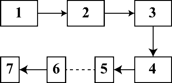
[0053] Such as figure 1 Shown, the medical intravenous infusion automatic monitoring system provided by the invention comprises:

[0054] Intravenous infusion set 1: used to infuse sterile liquid, electrolytes, and drugs into the patient's body through the vein;

[0055] Pressure sensor 2: Hang the intravenous infusion set under the pressure sensor (the sensor can be installed on the iron frame of the infusion set), the pressure signal is collected by the pressure sensor, and the pressure signal is converted into an electrical signal;

[0056] Signal amplifier 3: used to amplify the electrical signal transformed by the pressure sensor to increase the output power of the signal;

[0057] Analog-to-digital converter 4: used to convert the amplified signal, converting the continuous signal in analog form into discrete signal in digital form;

[0058] Specific model: Arduino Uno R3 Board (Italy product, source: http: / / item.taobao.com / item.htm?spm=a230r.1.14.48.NWpGKk&id=153214865...


PUM


Abstract

Disclosed is an automatic monitoring system for intravenous infusion. Intravenous infusion is a widely adopted medical method, namely blood, medicine and nutrient are directly infused into the vein of a patient. In many intravenous infusion processes, medical accidents are caused by flow speed of liquid, infusion time, the experience of medical staff and the like, the loss of the patient is caused, and even the life of the patient is threatened. The digital and intelligent automatic monitoring system for intravenous infusion comprises an intravenous infusion instrument, a pressure sensor, a signal amplifier, an analog-digital converter, a Bluetooth adapter, and a mobile terminal supporting the Android system. The automatic monitoring system for intravenous infusion adopts an advanced intelligent tablet computer system to monitor and record the whole process of intravenous infusion, not only is high in sensitivity and simple to assemble, but also achieves economic benefits, and has the advantages of cyclic utilization and environment protection.

Description

technical field [0001] The invention belongs to the technical field of medical auxiliary instrument systems, and relates to signal acquisition, signal processing, bluetooth wireless communication, and a data analysis method for a tablet computer. In particular, it relates to a remote control that can be carried out by using a hand-held mobile device through wireless communication. Background technique [0002] The existing infusion monitoring system is mainly divided into two types, one is to monitor the time by hand; the other is to monitor the liquid flow rate by infrared rays. [0003] The manual timekeeping method is relatively simple, mainly using stopwatches and counters, and the entire monitoring process is completed by the nurse on duty. The nurse starts timing with a stopwatch, and then uses a counter to count the number of drops of infusion liquid within the specified time. Finally, calculate the flow rate according to the specifications of different infusion set...

Claims


Application Information

Patent Timeline
Patent Type & Authority Applications(China)
IPC IPC(8): A61M5/172
Inventor 赵一泽
Owner 赵一泽
Learn More