Coolant conditioning system and method for a fuel processing subsystem

a technology of fuel processing subsystem and cooling system, which is applied in the direction of indirect heat exchangers, electrochemical generators, lighting and heating apparatus, etc., can solve the problems of difficult implementation of approaches and condensation

Inactive Publication Date: 2005-07-28
MODINE MFG CO
View PDF4 Cites 3 Cited by
  • Summary
  • Abstract
  • Description
  • Claims
  • Application Information

AI Technical Summary

Benefits of technology

[0032] In accordance with one form, the flow rate of the portion of the coolant under normal operating conditions is less than the desired flow rate.

Problems solved by technology

However, such an approach can be difficult to implement.
For example, because a liquid coolant is generally at a much lower temperature than the reformate that is being cooled, the problem of condensation may occur in the reformate flow.
This problem is especially important because condensed liquids, such as water, in the reformate stream can deactivate the catalyst that is utilized in CO removal or hydrogen purification units in fuel processing subsystems.

Method used


Image

  • Coolant conditioning system and method for a fuel processing subsystem
  • Coolant conditioning system and method for a fuel processing subsystem
  • Coolant conditioning system and method for a fuel processing subsystem

Examples


Embodiment Construction

[0044] While the present invention is susceptible of embodiment in many different forms, there are shown in the drawings and will be described herein in detail specific embodiments thereof with the understanding that the present disclosure is to be considered as an exemplification of the principles of the invention and is not intended to limit the invention to the specific embodiments illustrated.

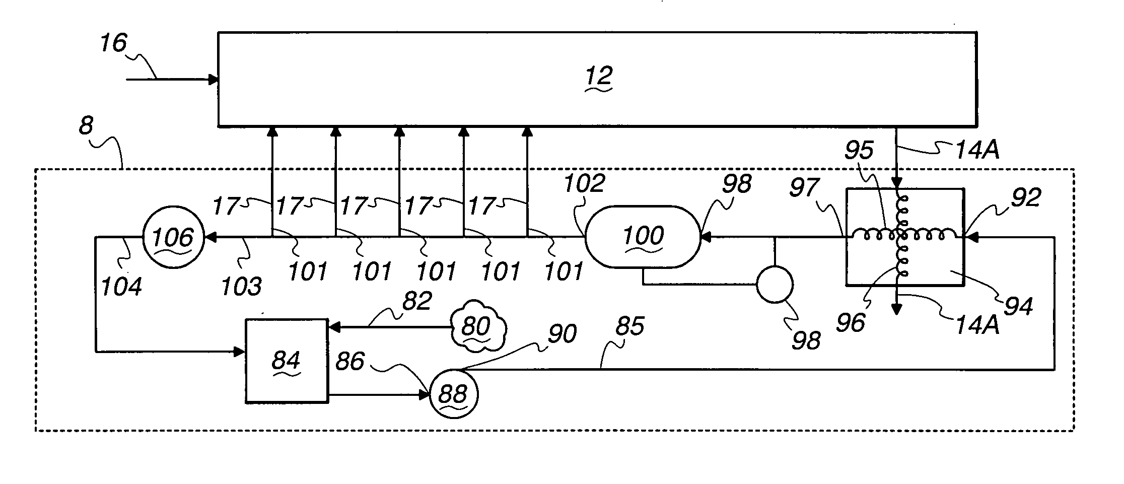
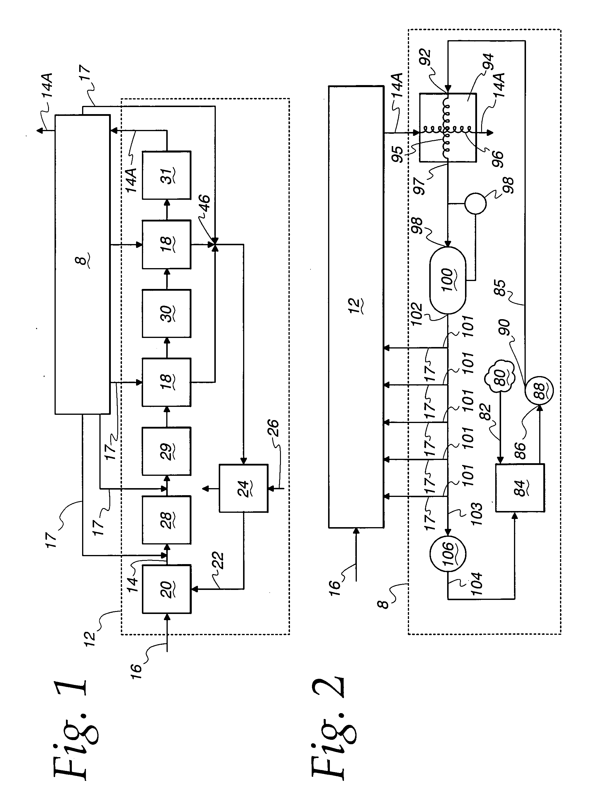
[0045] As seen in FIG. 1, a coolant conditioning system 8, in the preferred form of a process water conditioning system 8, is provided for use with a fuel processing subsystem, shown schematically at 12 for producing a reformate flow 14 from a hydrocarbon flow 16 and for reducing a level of carbon monoxide (CO) in the reformate flow 14 for use in a proton exchange membrane fuel cell system (not shown). As used in the specification, the phrase fuel flow is meant to encompass both the hydrocarbon flow 16 and the reformate flow 14. The process water conditioning system 8 provides one or more ...


PUM

PropertyMeasurementUnit
temperaturesaaaaaaaaaa
temperatureaaaaaaaaaa

Abstract

A coolant conditioning system is provided for supplying a coolant flow to a fuel processing subsystem. The coolant conditioning system includes a coolant preheater to transfer heat from a reformate flow to the coolant flow, a heater to selectively add heat to the coolant flow in response to the coolant flow dropping below a minimum temperature, at least one outlet flow path to provide a portion of the coolant flow to at least one fuel processing subsystem, and a return flow path to return a remainder of the coolant flow to a storage tank. The coolant conditioning system is dynamically controllable to provide a portion of the coolant flow above a minimum temperature to reduce or prevent condensation of the reformate flow in selected components of the fuel processing subsystem that receive the portion of the coolant flow.

Description

FIELD OF THE INVENTION [0001] This invention relates to coolant systems for fuel processing subsystems for fuel cell systems, and in more particular applications, to water conditioning systems for a reformate flow for fuel cell systems such as polymer electrolyte fuel cell systems, such as proton exchange membrane (PEM) fuel cell systems. BACKGROUND OF THE INVENTION [0002] In many PEM fuel cell systems, a fuel such as methane or a similar hydrocarbon fuel is converted into a hydrogen-rich stream for the anode side of the fuel cell. In many systems, humidified natural gas (methane) and air are chemically converted to a hydrogen-rich stream known as reformate by a fuel processing subsystem of the fuel cell system. This conversion takes place in a reformer where the hydrogen is catalytically released from the hydrocarbon fuel. A common type of reformer is an Auto-thermal Reactor (ATR), which uses air and steam as oxidizing reactants. As the hydrogen is liberated, a substantial amount o...

Claims


Application Information

Patent Timeline
Patent Type & Authority Applications(United States)
IPC IPC(8): C01B3/38C01B3/48F28D7/06H01M8/04H01M8/06
CPCC01B3/382Y02E60/50C01B2203/0244C01B2203/0288C01B2203/044C01B2203/047C01B2203/066C01B2203/0844C01B2203/142C01B2203/146C01B2203/82F28D7/06F28D2021/0019H01M8/04291H01M8/0612H01M8/0668C01B3/48H01M8/06
Inventor VALENSA, JEROENVOSS, MARK G.
Owner MODINE MFG CO
Why Eureka
Try Eureka