Casement window hinge

a casement window and hinge technology, applied in the direction of door/window fittings, multi-purpose tools, construction, etc., can solve the problems of window misalignment, hinge mechanism stress, fixed windows that cannot be opened for ventilation, etc., to increase the adjustability, increase the flexibility of the hinge, and increase the amount of adjustability

Inactive Publication Date: 2007-08-21
LIANG LUKE K +1
View PDF19 Cites 20 Cited by
  • Summary
  • Abstract
  • Description
  • Claims
  • Application Information

AI Technical Summary

Benefits of technology

[0010]It is still another object of the invention to provide an improved casement window hinge that will prevent the casement window from becoming misaligned over time.
[0011]It is a still further object of the invention to provide a casement window hinge that assists in preventing the casement window from sagging.
[0013]The casement hinge of the present invention includes a track that may be secured to a casement window frame, a sash arm extending from said track and a support arm that connects the sash arm and the track. On one side or edge of the track there is a rail for retaining a hinge shoe and permitting the shoe to travel along the rail in the track as the window is opened and closed. The sash arm is pivotally mounted at one end thereof on the track by means of a hinge shoe. The hinge shoe is connected to the sash arm by a suitable connection means such as a screw, pin or a rivet. The connection means should permit pivotal movement of the sash arm in relation to the shoe. The sash arm has another connection means which can also be a screw, pin or rivet, that connects the sash arm to the support arm at any one of a number of locations along the sash arm. The multiple connection points increase the adjustability of the hinge to fit any number of casement windows as well as correct minor errors in installation or sagging over time. The connection means joining the sash arm and the support arm should also permit pivotal movement of the two arms. The first shoe is preferably retained in the track to prevent it from becoming separated from the track and the shoe should be able to ride along the track longitudinally as necessary to permit movement of the window.
[0015]One end of the support arm is pivotally connected to the sash arm. The other end of the support arm is connected to a second shoe or gear rack. The second shoe has a fixed position on the track and permits the second end of the support arm to pivot about a pin during opening and closing of the window. In one embodiment of the present invention, the support arm is retained on the pin by a clip. The second shoe is preferably secured to the track through a orifice in the shoe that generally lines up with a orifice in the track by a screw or other means that preferably passes through the track orifice and enters the window frame. Preferably, the orifice or slot is oblong i.e., a relatively long narrow opening. The longer the slot in the shoe, the greater the amount of adjustability that is possible along the track of the hinge. This shape permits the shoe to be adjusted longitudinally. The screw will also provide further anchoring of the hinge to the window frame. The shoe has a recessed base section that has the orifice for securing the shoe to the track. There is also a second orifice that receives a rivet for pivotally securing the support arm to the shoe. Adjacent the recessed base section there may be a raised ledge. On the side of the ledge that is opposite the recessed base section there is a tongue that is provided with a plurality of teeth. Running along the rear of the shoe is a ridge or flange that helps retains the second hinge shoe to the rail. The gear wheel is rotatably secured to the track by a rivet. The rivet is preferably slotted in some manner to permit a screw driver or other type of driver to turn the gear wheel. The teeth on the wheel mesh with the teeth on the tongue and as the gear wheel is turned the tongue is moved in a longitudinal direction along the track. This permits the second shoe to be adjusted to increase the flexibility of the hinge of the present invention in many applications. In particular, the adjustability of the second shoe increases the ease of installation, reduces the effects of sagging in the window and reduces the effects of wear and tear on the components of the hinge over time.

Problems solved by technology

Fixed windows for example are not able to be opened for ventilation.
The hinge mechanism in casement windows is subject to stress over time.
There is a risk that the window may become misaligned whether through poor installation, the weight of the window, weathering or moisture or simply just settling of the house.
One of the problems that may be encountered over time is the shifting of the fixed track pivot due to shifting of the window, the window frame, etc., which may result in sagging of the sash.
In the event the sash sags, there is a risk that the window may not seal properly and permit moisture and cold air to enter.
Another problem that may be caused by sagging of the sash is difficulty in opening and closing the window.
In these windows, however, repeated adjustment of the track could result in the mounting assembly for the track undergoing fatigue and gradually loosening.
In addition, to adjust the track of many casement windows the window must be open and it is difficult to determine whether the window will close satisfactorily when the adjustment is made.
As a result, there is a need for an improved hinge for casement windows which will permit the installer, repair person and / or home owner to adjust the hinge either during installation or later to compensate for sagging of the sash, frames being out of alignment, and other problems with the casement windows that made it difficult to install the windows or adjust their movement once they have been installed in a window.

Method used


Image

  • Casement window hinge
  • Casement window hinge
  • Casement window hinge

Examples


Embodiment Construction

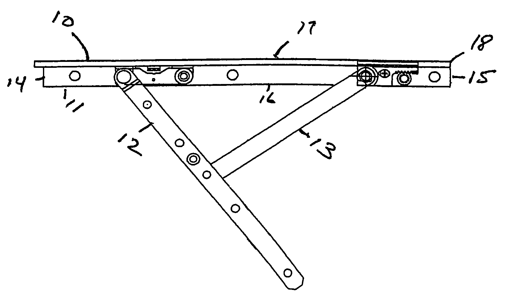
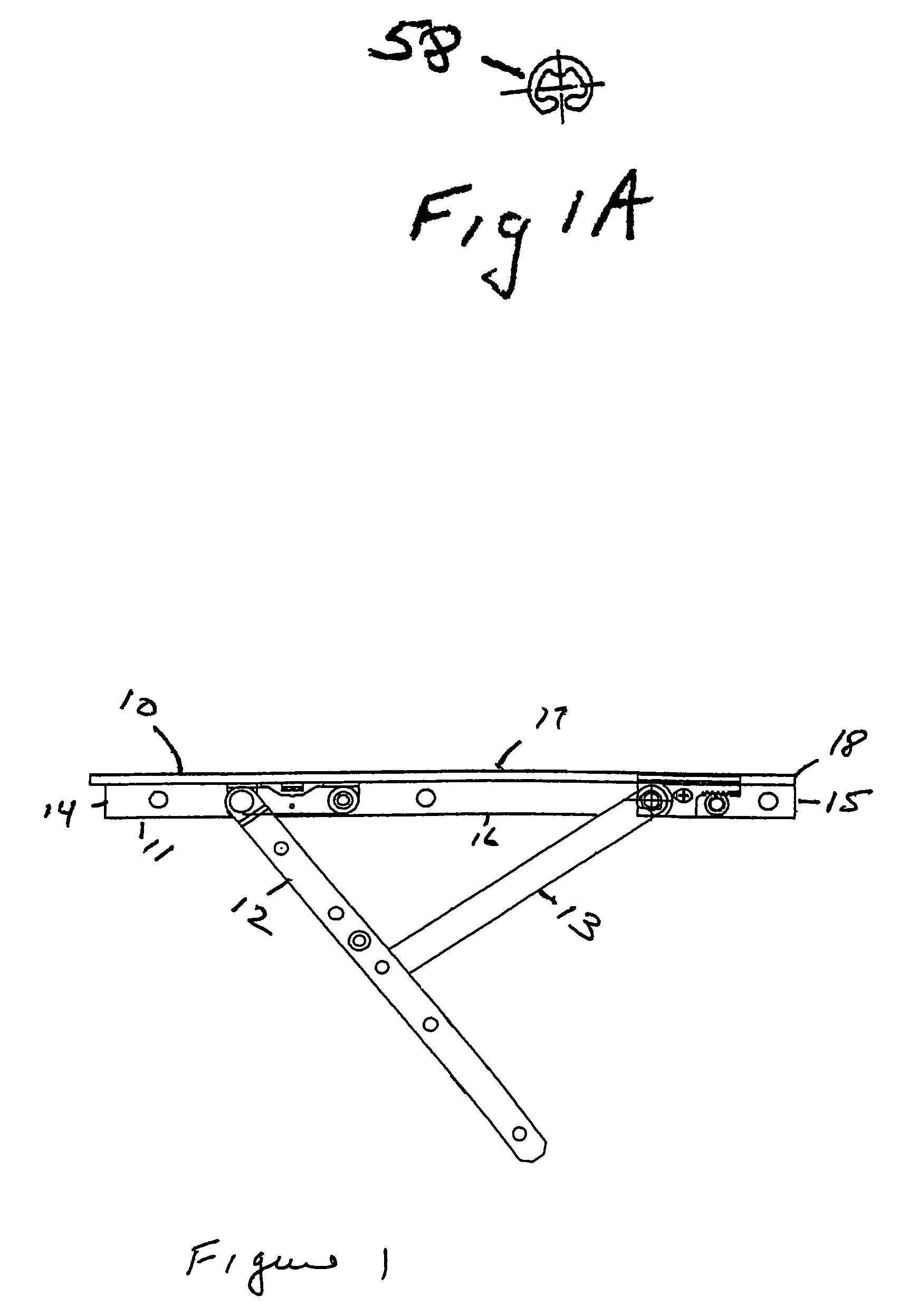
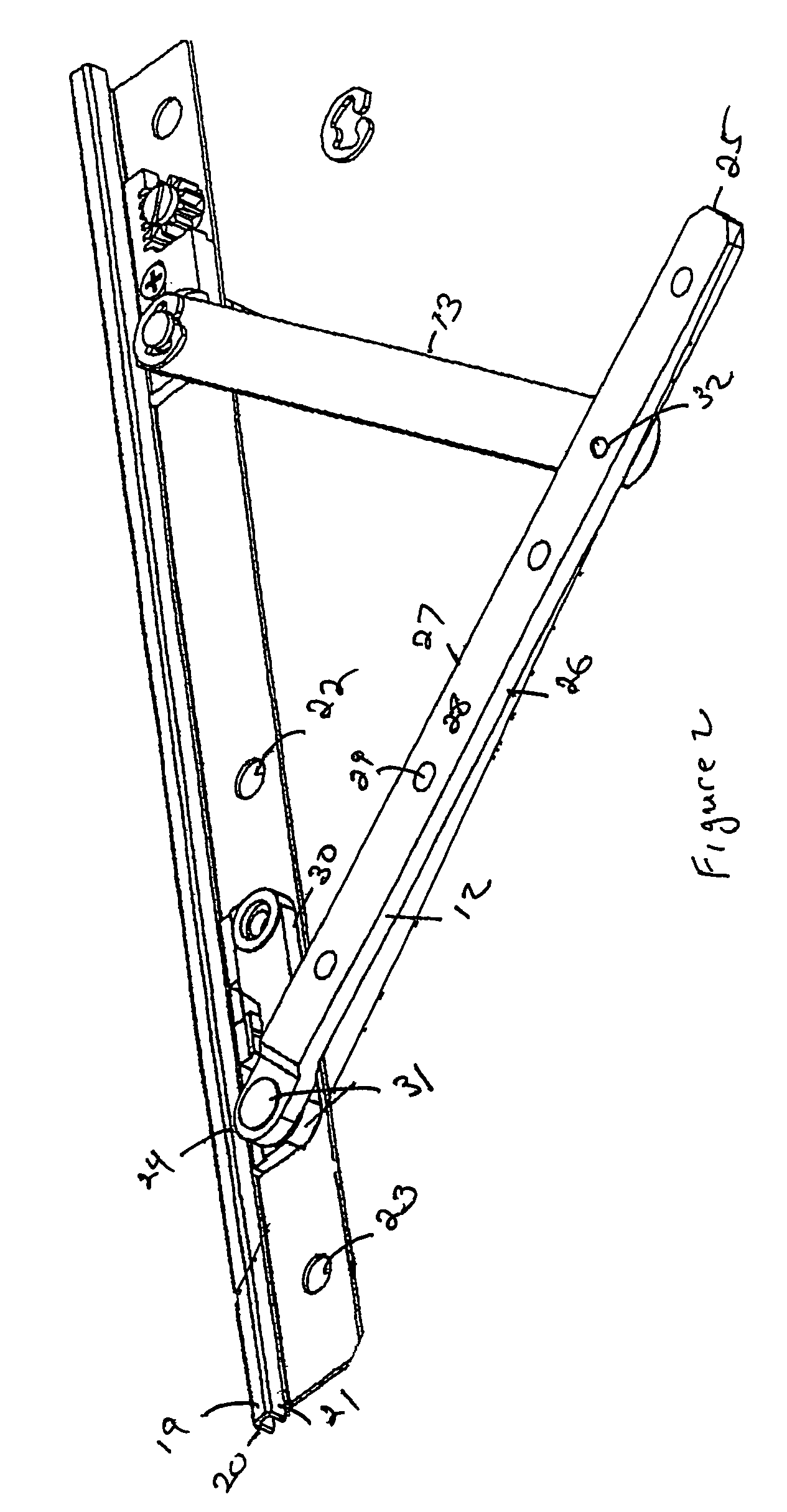
[0034]A preferred embodiment of the casement hinge 10 of the present invention is shown in FIG. 1. The hinge includes a track 11, a sash arm 12 and a support arm 13. The track 11 is preferably a generally rectangular sheet of metal or plastic having a first end 14 and a second end 15. The ends are joined together by a first side 16 and a second side 17. Second side 17 preferably is provided with a rail 18 for retaining the hinge shoe and permitting it to travel along the rail in the track 11. The rail may be any suitable means to retain the shoe and permit it to ride along the rail. As seen in FIG. 2, the rail has a rail top member 19, and rail side members 20 and 21. The rail side member 21 may be adhered to the track by any suitable means such as welding or it may be integral with the track. The track is provided with one or more orifices 22 and 23 that enable the track to be secured to the frame of the casement window by screws or other fastening devices.

[0035]Extending from the ...


PUM


Abstract

An improved shoe for a casement window hinge is disclosed. The hinge has a base with a front end and a rear end and two sides. The base has a ridge on the rear end for securing the base to a track and a tongue extending from one of the sides. The tongue has a plurality of teeth extending from a side of the tongue. A gear wheel is adapted to be rotatably secured to a track. The gear wheel has a plurality of teeth about its circumference which mesh with the teeth on the tongue. The rotation of the gear wheel causes the base of the hinge to move longitudinally in relation to the track.

Description

FIELD OF THE INVENTION[0001]The present invention is directed to hinges for casement windows and more particularly, improvements in the adjustability of such hinges.BACKGROUND OF THE INVENTION[0002]In most construction there are a variety of window types that are available. These windows may include fixed, double hung, casement, transom, etc. Each window has certain benefits and drawbacks. Fixed windows for example are not able to be opened for ventilation. Double hung windows were originally designed to let cooler air in the lower portion and hotter air out the upper portion. Casement windows are advantageous in that the entire window can open.[0003]Traditional double hung windows ride in a track and are raised and lowered for ventilation. Casement windows are windows that are mounted in a frame and are hingedly connected on one side to a frame, or to the top and bottom, by usually a pair of hinges. Casement windows typically open outwardly, although, there are some casement type w...

Claims


Application Information

Patent Timeline
Patent Type & Authority Patents(United States)
IPC IPC(8): E05D3/06E05D7/04E05D15/30E05D15/44
CPCE05D7/0415E05D15/30E05D15/44E05Y2900/148Y10T16/541Y10T16/5324Y10T16/5323Y10T16/532Y10T16/547
Inventor LIANG, LUKE K.LIANG, TONG
Owner LIANG LUKE K
Why Eureka
Try Eureka