Magazine loader

a loader and magazine technology, applied in the field of bullet loaders, can solve the problems of time-consuming process, difficult inserting of each bullet, and difficulty in reloading bullets into spent magazines

Inactive Publication Date: 2007-08-21
FARLEY II ALLEN D
View PDF11 Cites 69 Cited by
  • Summary
  • Abstract
  • Description
  • Claims
  • Application Information

AI Technical Summary

Problems solved by technology

As the magazine is being loaded, each succeeding round of ammunition compresses the spring further and each bullet becomes harder to insert.
On the other hand, reloading bullets into the spent magazine is known to be problematic.
This process is time consuming, and quite often frustrating, particularly when the resistance of the compression spring begins to increase.
While it does facilitate in solving the problem of reloading, the requirement of removal and reinsertion makes its use somewhat tedious.
Howard is also somewhat helpful, but difficulties may be encountered in holding the device in place against the magazine.

Method used


Image

  • Magazine loader
  • Magazine loader
  • Magazine loader

Examples


Embodiment Construction

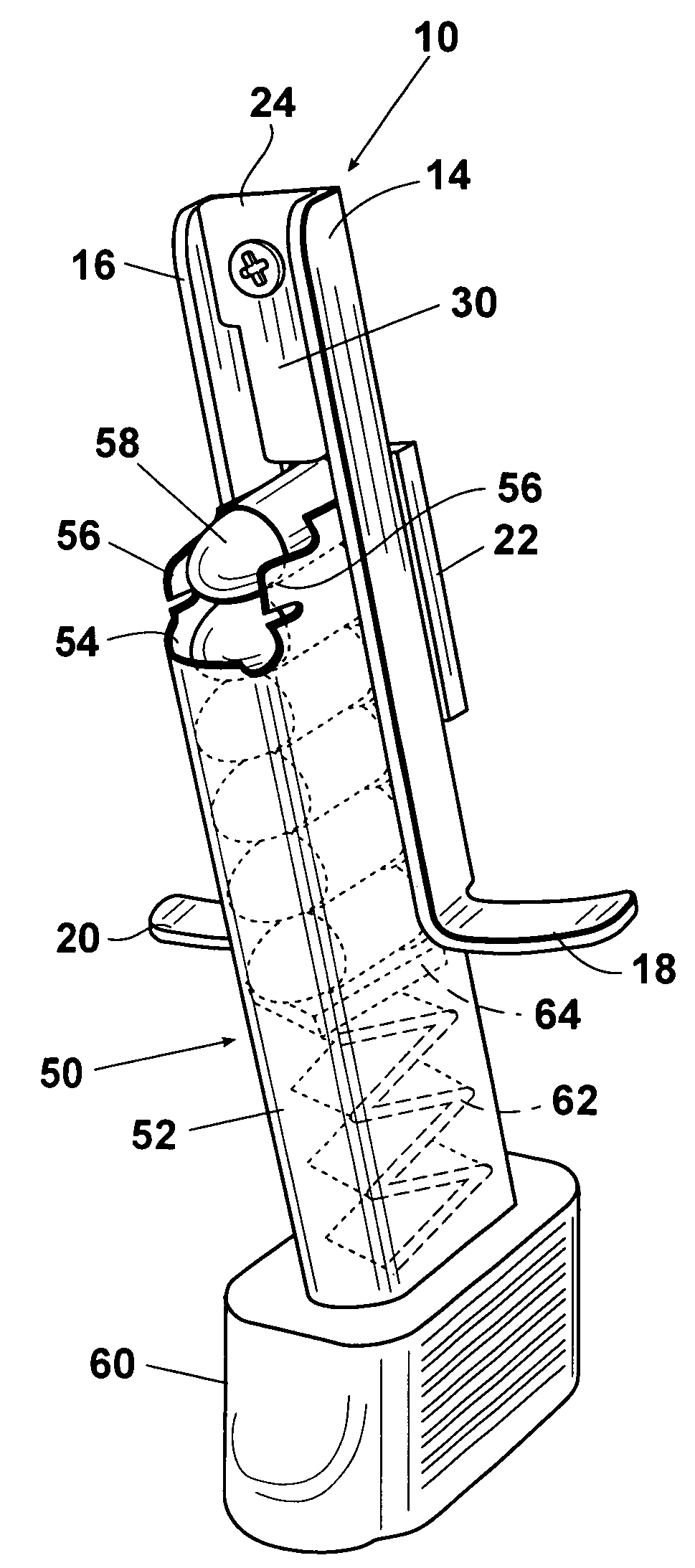
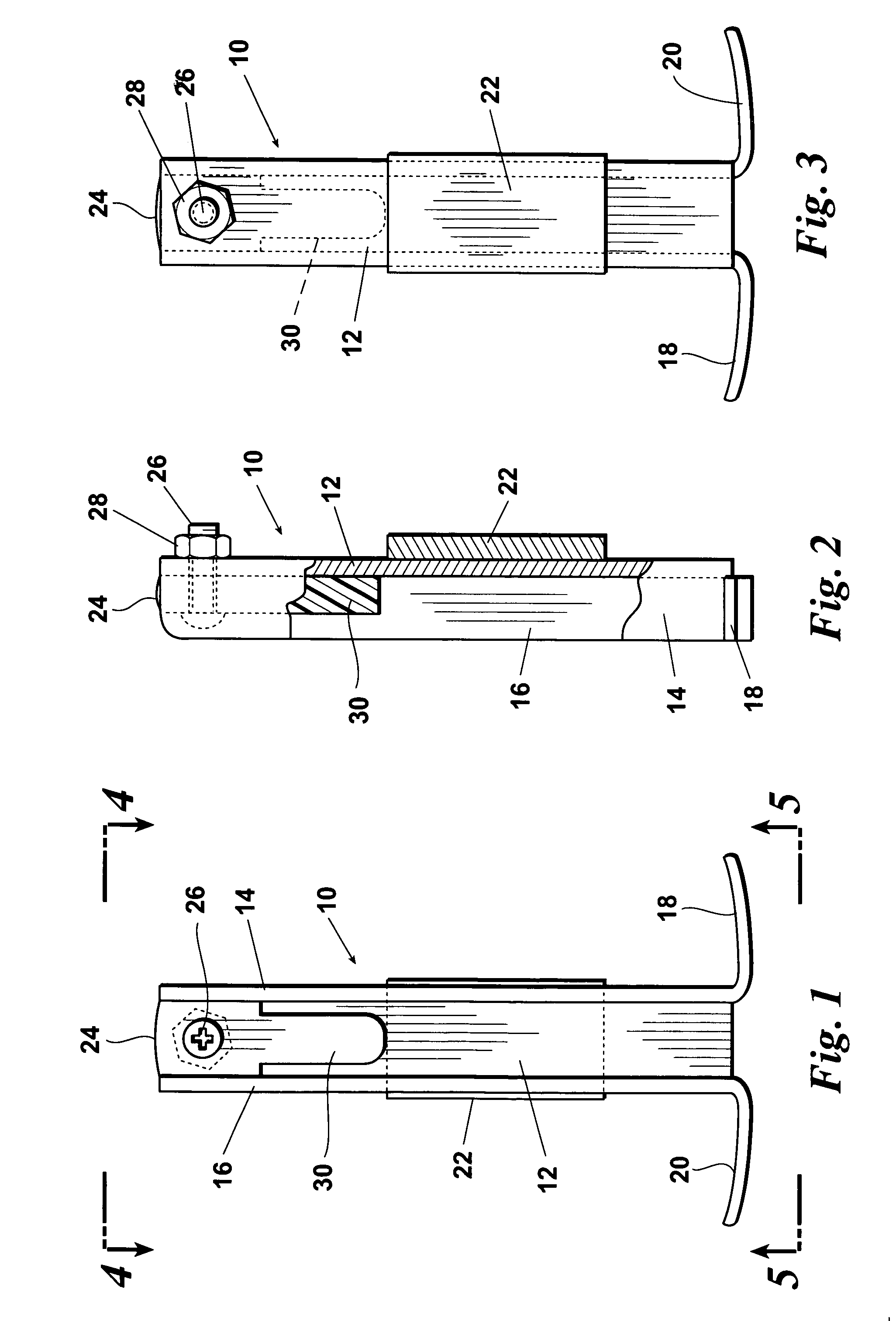
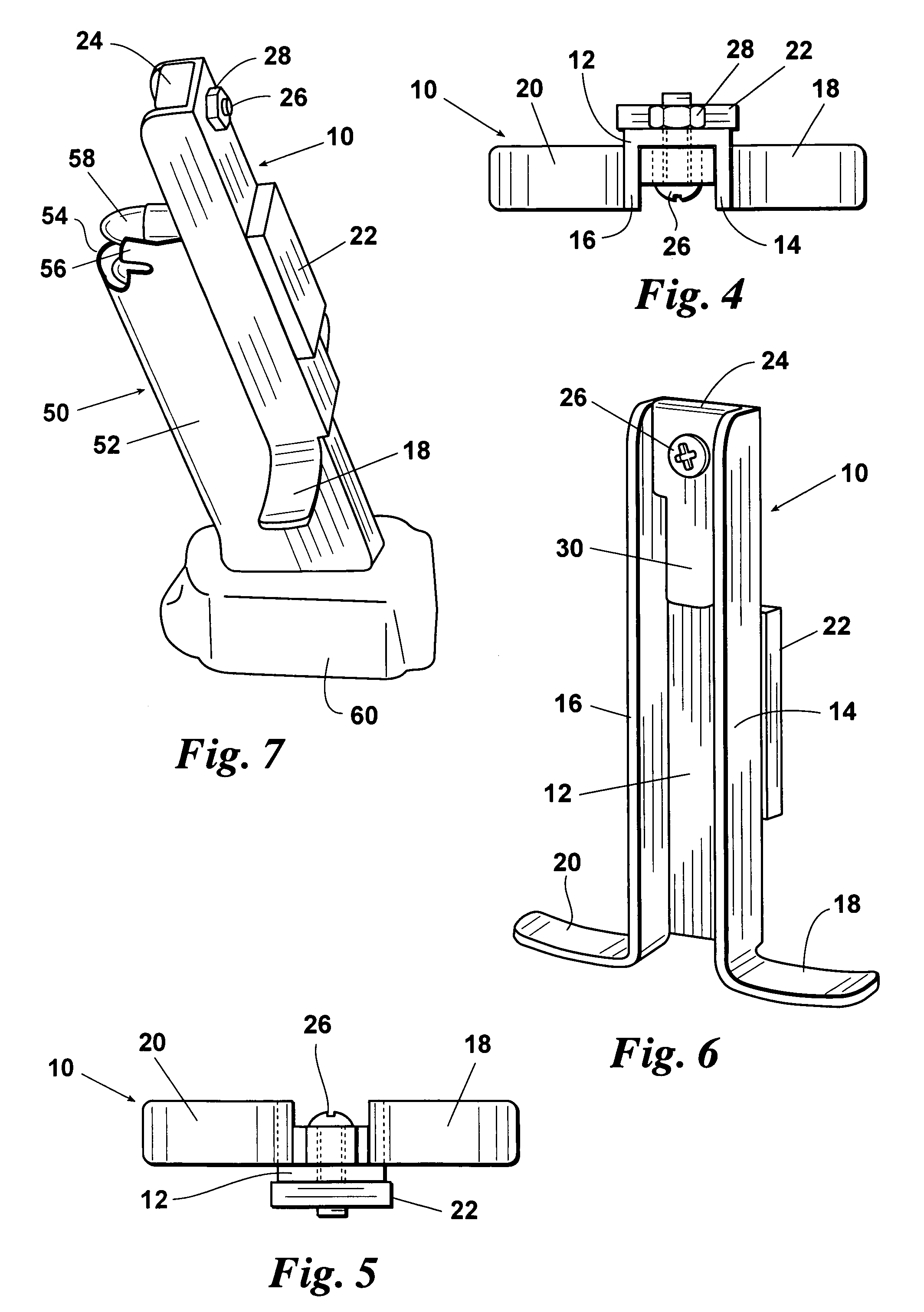
[0021]Referring to the Drawings in detail, FIG. 1 shows a channel shaped member 10, purely for the sake of comparison purposes, approximately three and one half inches high. The channel 10 is preferably made of aluminum for reasons which will be hereinafter more readily understood. The channel 10 is formed by a flat back portion 12 and a pair of forwardly extending vertical plates 14 and 16 which extend for the full vertical height of the channel member 10. At the bottom of the legs 14 and 16 are arms 18 and 20 which extend horizontally outwardly and which are accessible to the fingers of the shooter's hand. Secured to the back 12 of the channel member 10 is a magnetic plate 22 which is approximately two inches high by one inch wide. The magnetic plate 22 can be attached by any convenient adhesive or welding material which is capable of bonding the magnetic plate 22 to the aluminum back 12.

[0022]At the upper end of the channel member 10 is a tab 24 which is held in place by means of...


PUM


Abstract

A loader for a magazine having an upper open end, a lower closed end, a forward vertical side edge and a rear vertical flat side edge, loader having a vertical channel for receiving therein the rear flat edge of the cartridge, the channel being formed by a pair of flat vertical side members spaced apart in parallel relation and having a rear flat edge where it slidably engages the rear flat edge of the magazine, the magazine being made of ferrous metal and the loader being made of non-ferrous material. A vertically extending tab is mounted in the upper portion of the channel and is provided with a downwardly vertically extending plunger mounted at the lower end of the tab for engaging the edge of an uppermost bullet mounted within the magazine. A pair of outwardly and horizontally extending arms are mounted at the lower ends of the flat vertical sides of the loader, the magazine being adapted to receive a plurality of vertically stacked bullets therein, a spring mounted internally in the magazine for urging the bullets upwardly towards the open end of the magazine and against a retaining means which holds the bullets within the magazine whereby, when the user's fingers engage the arms on the loader and urge the loader downwardly against the action of the spring within the magazine, the uppermost bullet is urged away from the retaining means at the top of the magazine and whereby an additional bullet can be inserted into the magazine above the then uppermost bullet after which the loader can be slid upwardly so that the plunger is completely above the last added bullet to permit the last added bullet to be pushed in by hand against the inner flat edge of the magazine, the loader being maintained in sliding contact within the magazine by virtue of a magnet mounted on the rear of the loader.

Description

BACKGROUND OF THE INVENTION[0001]1. Field of the Invention[0002]This invention relates to a bullet loader, more particularly, to a device for reloading bullets into the magazine or clip of a firearm.[0003]2. Prior Art[0004]Many small arms, including both rifles and hand guns are provided with magazines or clips in which the bullets are stored for immediate use. In these firearms, ammunition is placed into an elongated, generally rectangular, container, known as a magazine or clip, which is then fitted into a portion of the firearm approximate to the firing chamber; in the case of a pistol, this clip or magazine can be inserted into the handle of the gun. The magazine or clip is closed on five (5) sides of the rectangular shape and open on one rectangular shaped end. Such magazines or clips are spring loaded and are further provided with retaining members over the open end. Ammunition can be placed into the open end of the magazine, piece by piece, and each piece slips past the retai...

Claims


Application Information

Patent Timeline
Patent Type & Authority Patents(United States)
IPC IPC(8): F41A9/83
CPCF41A9/83
Inventor FARLEY, ALLEN D.
Owner FARLEY II ALLEN D
Why Eureka
Try Eureka