Adjustable fixator

a fixator and adjustable technology, applied in the field of orthopaedic surgical devices, can solve the problems of difficult repositioning or adjusting the bone screws following implantation, difficult manipulation of implants, and high cost of surgery

Active Publication Date: 2007-08-28
AO TECH AG +1
View PDF161 Cites 107 Cited by
  • Summary
  • Abstract
  • Description
  • Claims
  • Application Information

AI Technical Summary

Benefits of technology

[0019]The slit of the joint assembly body may include first and second sections, with the sections being oriented at an ...

Problems solved by technology

One limitation associated with bone screws, however, is that repositioning or adjusting the bone screws following implantation is difficult.
However, as with bone screws, removal of the pins may be required ...

Method used


Image

  • Adjustable fixator
  • Adjustable fixator
  • Adjustable fixator

Examples


Embodiment Construction

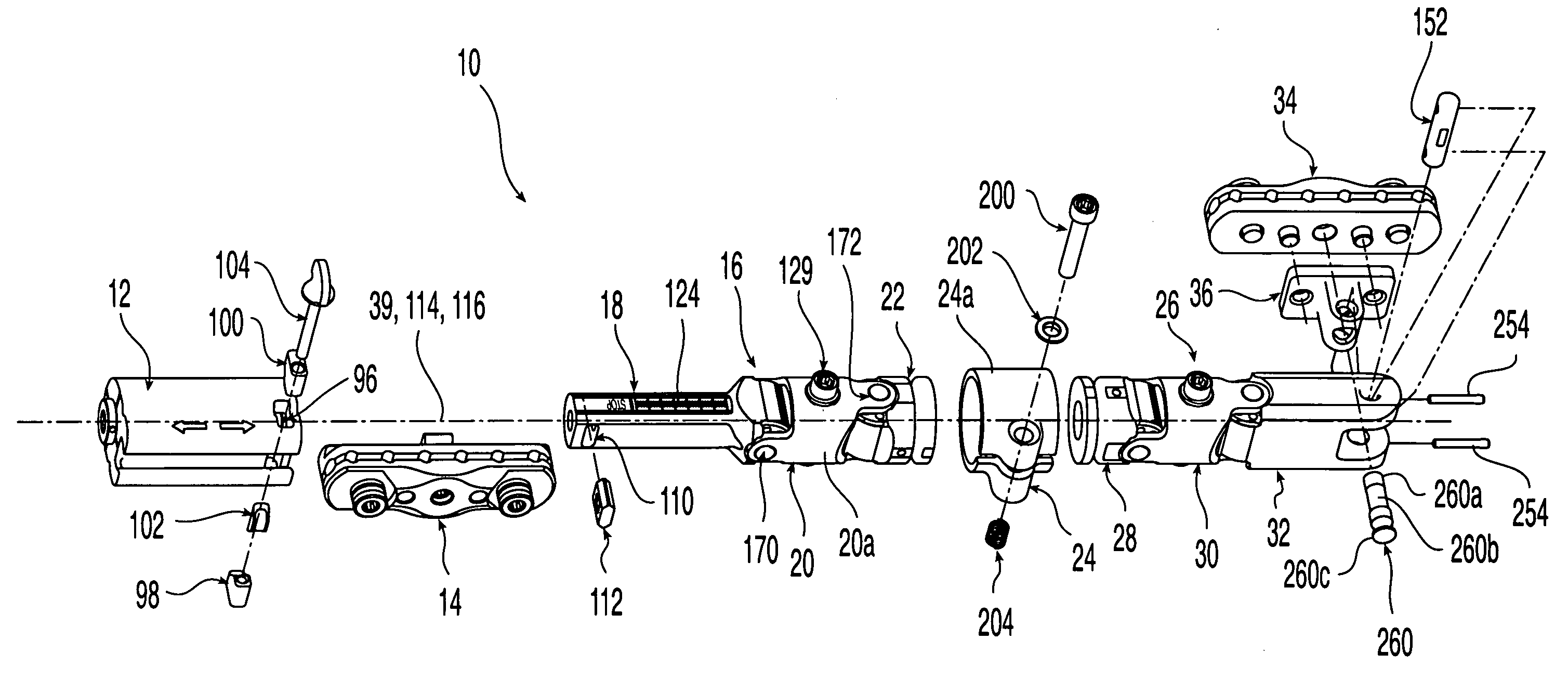
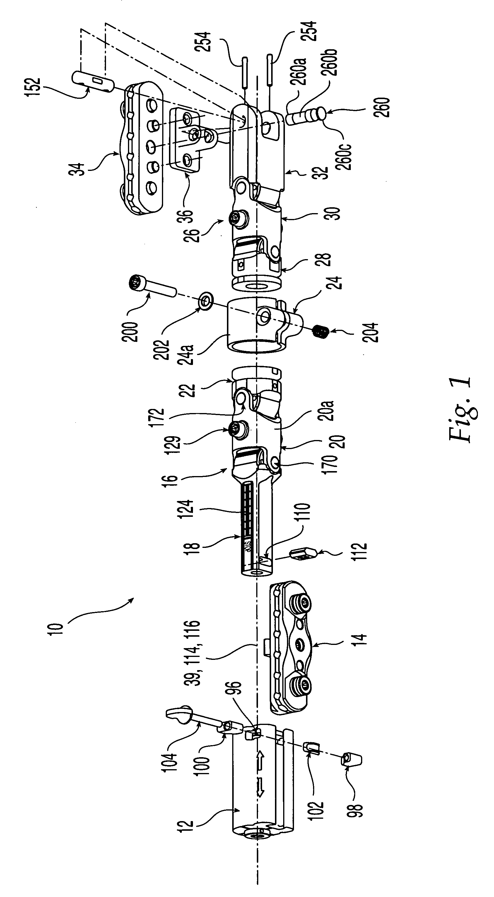
[0087]Referring initially to FIG. 1, an adjustable fixator 10 according to one embodiment of the present invention is shown. Fixator 10 is suitable for stabilizing and rigidly fixing bone fragments or segments with respect to each other, and may be made of any suitable material such as titanium, stainless steel, polymers, alloys, composites, or other materials. Fixator 10 includes a distractor body 12 and associated distractor clamp assembly 14, as well as a first body portion 16 with a distractor bar 18, distractor joint assembly 20, and coupling 22. Distractor body 12 and associated components may be used for distraction and compression. In addition, fixator 10 includes a central joint assembly 24, along with a second body portion 26 having a coupling 28, a T-clamp joint assembly 30, and a T-clamp link 32. A T-clamp assembly 34 is preferably secured to a T-clamp pivot 36 that is pivotably associated with T-clamp link 32.

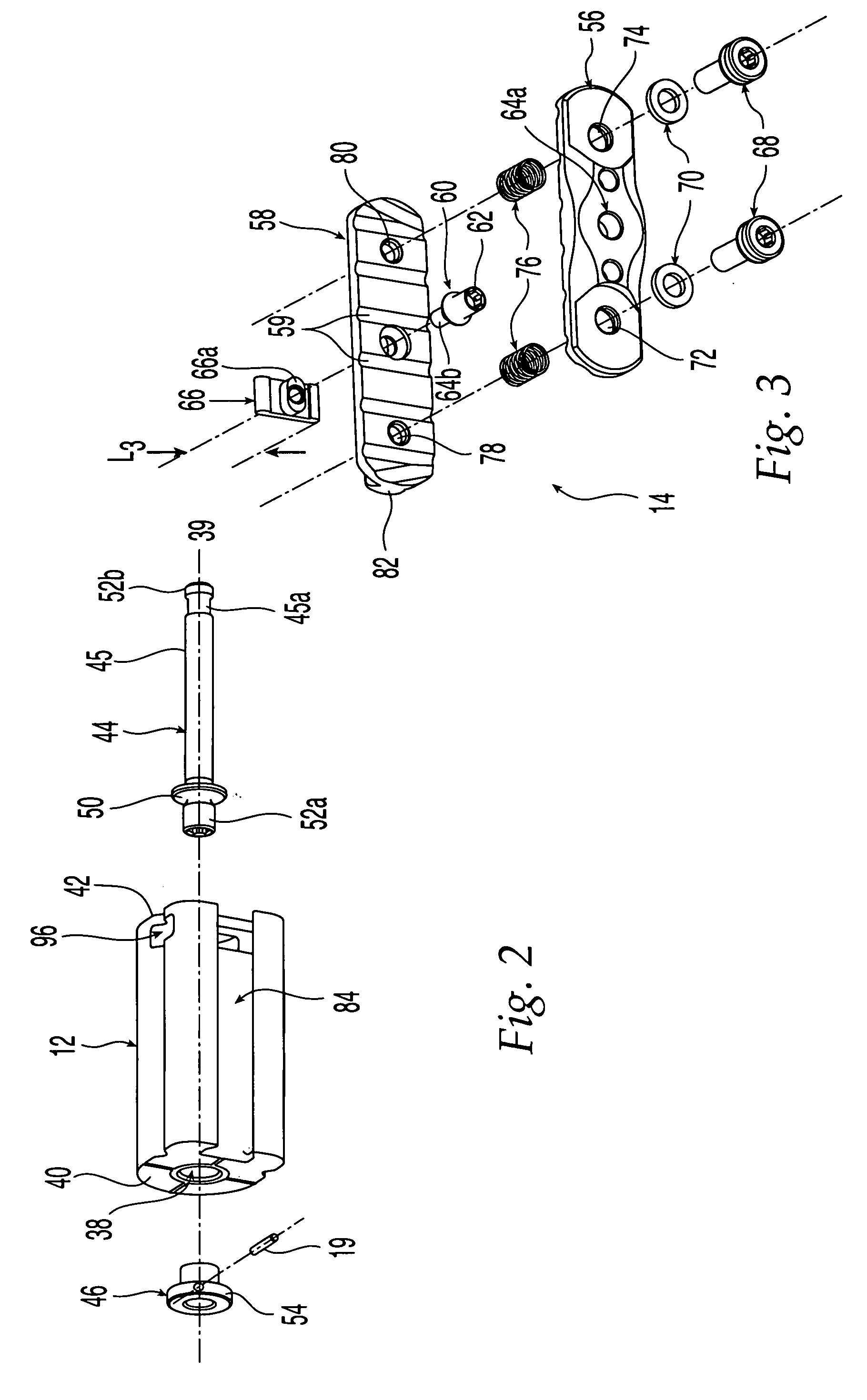
[0088]Turning to FIGS. 2 and 2A-2C, distractor body 12 includ...


PUM


Abstract

A bone fixator for securing a first bone portion in a position relative to second bone portion is disclosed, including at least two clamping assemblies each for receiving at least one bone pin and a main body disposed between the clamping assemblies. The main body includes at least one joint for orienting the clamping assemblies with respect to each other. The at least one joint may permit pivoting or rotation. Some joints permit the articulation of several components to be simultaneously and releasably lockable.

Description

CROSS-REFERENCE TO RELATED APPLICATIONS[0001]The benefit of U.S. Provisional Application No. 60 / 327,294 filed Oct. 9, 2001 is claimed under 35 U.S.C. § 119(e).FIELD OF THE INVENTION[0002]The present invention relates generally to orthopaedic surgical devices, and more particularly to an adjustable fixator for securing bone segments.BACKGROUND OF THE INVENTION[0003]Various types of orthopaedic devices are known for the fixation of bone fragments. Such devices typically are used to stabilize bones by maintaining fractured bone portions in relatively fixed positions with respect to each other. The alignment and stability provided by the devices promotes the healing of fractures, allowing proper fusion to occur.[0004]Internal fixation devices include bone screws, which are used in a variety of orthopaedic applications for fixation of bone fragments. Bone fragments may be positioned in a desired configuration, and one or more holes may be drilled and tapped across the fracture. Compressi...

Claims


Application Information

Patent Timeline
IPC IPC(8): A61B5/04A61B17/58A61B17/64A61B17/66
CPCA61B17/6458A61B17/6425A61B17/6416A61B17/66
Inventor LANGMAID, MICHAEL N.MAUGHAN, THOMAS JOSEPHROTH, CHRISTOPH ANDREASMAZZIO, MICHAEL C.
Owner AO TECH AG
Why Eureka
Try Eureka