Microcircuit card attached to an adapter base, card base and manufacturing method

a technology of adapter base and micro-circuit card, which is applied in the field of micro-circuit cards, can solve the problems of limiting the number of cards rejected, limiting the number of cards, and obvious cost (for the design and manufacture of the machine) and flexibility, and achieves the effect of convenient production

Active Publication Date: 2007-09-04
OBERTHUR CARD SYST
View PDF18 Cites 47 Cited by
  • Summary
  • Abstract
  • Description
  • Claims
  • Application Information

AI Technical Summary

Benefits of technology

[0014]The internal part (and the microcircuit which is joined to it) is fixed to the base in a manner such that the card so obtained can be transported, carried about and used in the same way that a card originally manufactured in the format of the base would be used. For example, the card can be turned over so that the opening of the said cavity faces downward without the second card (or that part of the second card) being able to fall out.
[0042]This method offers the advantage of permitting the use of machines adapted to cards of common format (for example, conforming to Standard ISO7816) to carry out part of the production operations, in particular the mounting of the microcircuit or the module in a base containing the future internal part. For example, it is possible to mount the module on a format ID-000 card using a commercial machine and then place the format ID-000 module on the base, for example in the form of a “Canal+”® key. This makes it unnecessary to use a module mounting machine dedicated to the form of the keys of the type mentioned above.

Problems solved by technology

These machine tools are relatively sophisticated and costly, having to be capable of processing a high rate of throughput of cards, typically 4,000 cards per hour, while limiting the number of cards rejected.
In order to mount modules on specially shaped cards, it is thus necessary in principle to adapt the above-mentioned machine tools, or to construct new machine tools dedicated to each specific form of card, which presents obvious problems of cost (for the design and manufacture of the machines) and of flexibility (adaptation to the production load of the different forms of card).
However it is no longer possible subsequently for this card to be read by a card reader designed to read cards of a larger format, in particular the initial ID-1 format.

Method used


Image

  • Microcircuit card attached to an adapter base, card base and manufacturing method
  • Microcircuit card attached to an adapter base, card base and manufacturing method
  • Microcircuit card attached to an adapter base, card base and manufacturing method

Examples


Embodiment Construction

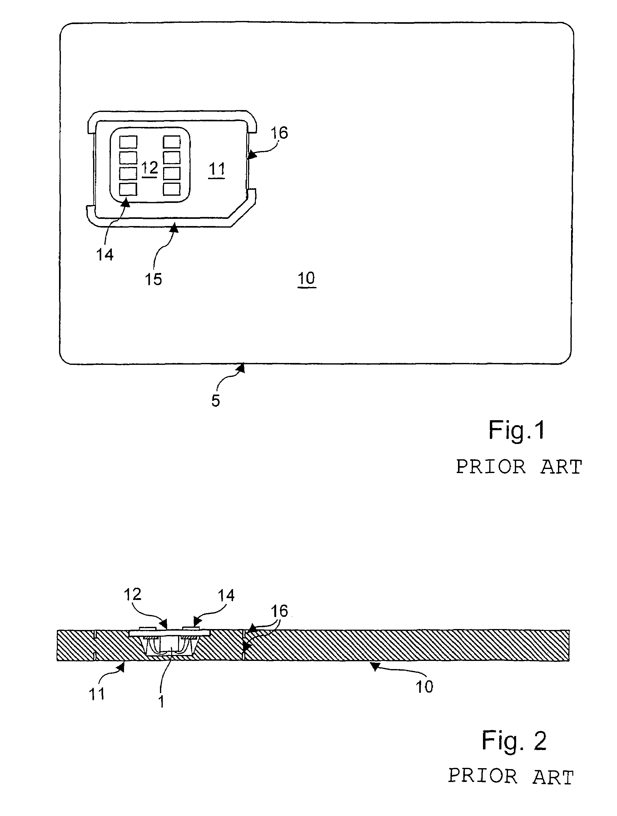
[0073]FIGS. 1 and 2 show a card, known as such, of SIM plug-in type. Such a card 5 comprises a base 10 of format ID-1 in which have been formed a cut-out 15 and weakened zones 16, delineating a SIM card 11. The SIM card 11 can be detached from its base 10 by the customer, for example when he wants to insert the card in his telephone adapted to receive cards in format ID-000. The SIM card11 comprises a module 12 mounted on the ID-1 card before cutting and presplitting of the SIM card 11. In the example under consideration, the module 12 comprises a printed circuit provided on its front surface (shown upwards here) with contacts 14 enabling the card to communicate with a reader, and on its rear surface, a microcircuit 1 fixed in place with adhesive and connected electrically by wires to the printed circuit. In a variant not shown here, the module has no contacts, being adapted to be connected without contacts. This module is fixed in a cavity of the base card which has a closed bottom...


PUM


Abstract

A microcircuit card (31) includes a microcircuit and a card body. The card body is formed of a base (10) in which is formed a cavity provided with a bottom and an internal part fixed in the cavity and to which the microcircuit is joined, the internal part and the microcircuit (12) together constituting at least a part of a second microcircuit card (11) including at least a part of the body of the second card.

Description

FIELD OF THE INVENTION AND TECHNICAL PROBLEM[0001]The invention concerns the field of microcircuit cards.[0002]It is known that a microcircuit card comprises a card body to which is fixed a module comprising a printed circuit on which is fixed an integrated circuit also known as a “chip”. In practice, this chip is fixed in a cavity in the card body, the bottom of which is closed so that it contributes to the secure attaching of the chip.[0003]Such cards are designed to be inserted in a reader equipped with suitable means for cooperating with the integrated circuit for the purpose of exchanging data and / or commands. This cooperation may be effected by means of contact pads provided on the module (conforming in practice to Standard ISO78), or at a distance, without contact. For this cooperation to be able to take place, the card, and therefore the card body, must have a format that the reader in question is capable of reading, and the module must have a given configuration with respec...

Claims


Application Information

Patent Timeline
Patent Type & Authority Patents(United States)
IPC IPC(8): G06K7/00G06K19/00G06K19/06G06K19/077
CPCG06K19/005G06K19/048G06K19/07739G06K19/07745G06K19/07749H01L2224/48091H01L2224/48227H01L2924/01079H01L2924/00014
Inventor AMIOT, LUCIENMOSTELLER, BARRY
Owner OBERTHUR CARD SYST
Why Eureka
Try Eureka