Electrical connector
a technology of electrical connectors and connectors, which is applied in the direction of fixed connections, coupling device connections, electrical apparatus construction details, etc., can solve the problems of not meeting the need for multi-directional flexibility of terminals, and the need for in the industry to be addressed, so as to achieve resistance capability and terminal durability, improve the effect of a flaw and ensure the connection of electrical and mechanical connections
- Summary
- Abstract
- Description
- Claims
- Application Information
AI Technical Summary
Benefits of technology
Problems solved by technology
Method used
Image
Examples
first embodiment
[0022]Referring to FIGS. 4-6, an electrical connector 200 for connecting a chip module 70 to a printed circuit 90 in accordance with the present invention includes an insulative housing 50 defining a number of passageways 56 therein and a number of conductive terminals 60 residing in the corresponding passageways 56, respectively.
[0023]Individual elements of the electrical connector 200 will now be described in greater detail. The housing 50 includes a supporting surface 52 to accept the chip module 70 thereon and an opposite mounting surface 54 facing to a printed circuit board 70. A number of passageways 56 extending between the supporting surface 52 and the mounting surface 54 are arranged in the housing 50 in a predetermined matrix fashion. The passageway 56 defines a rectangular receiving channel 562 and an elongate securing channel 564 commutated with the receiving channel 562.
[0024]As shown in FIG. 5 and FIG. 6, a number of conductive terminals 60 made by stamping and bending...
second embodiment
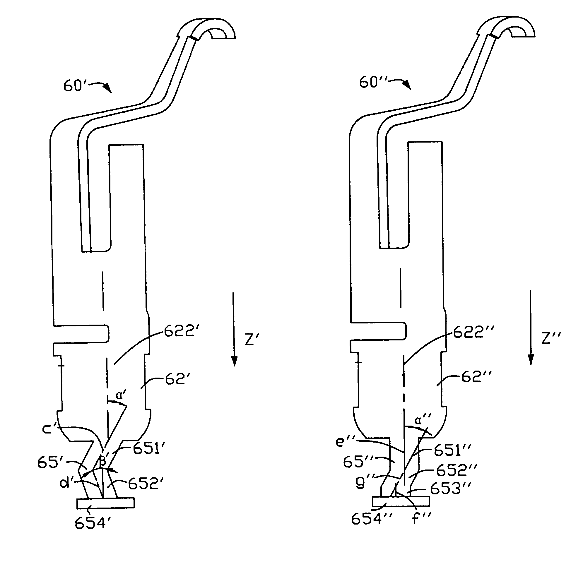
[0027]Referring to FIGS. 7-8, an electrical connector 200′ of the second embodiment in accordance with the invention comprises a housing 50′ and a plurality of terminals 60 received in the housing 50′.
[0028]In this embodiment, the terminal 60′ comprises a securing portion 62′, a connecting portion 66′ extending form the securing portion 62′ and a tail portion 64 extending form a lower end of the securing portion 62′, and a transitional portion 65′ formed between the tail portion 64′ and the securing portion 62′. The securing portion 62′ defines a securing surface 622′ and the transitional portion 65′ is disposed as two parts comprising a first twist portion 651′ and a second twist portion 652′. The centerlines of the first twist portion 651′ and the second twist portion 652′ projected on the plane of the securing surface defined by are lines c′, d′. The inserting direction of the terminals inserted into the housing is direction Z′. The lines c′, d′ are separated angles α′, β′ with Z...
third embodiment
[0029]As illustrated in FIG. 9 to FIG. 10, an electrical connector 200″ of a third embodiment in accordance with the invention comprises a housing 50″ and a plurality of terminals 60″ received in.
[0030]In this embodiment, the terminal 60″ comprises a securing portion 62″, a connecting portion 66″ extending form the securing portion 62″ and a tail portion 64″ extending form a lower end of the securing portion 62″, and a transitional portion 65″ formed between the tail portion 64″ and the securing portion 62″. The securing portion 62″ defines a securing surface 622″ and the transitional portion 65″ is disposed as three parts comprising a vertical buffering portion 651″, a horizontal buffering portion 653″ and a twist portion 652″ disposed between the vertical buffering portion 651″ and the horizontal buffering portion 653″. The centerlines of the vertical buffering portion 651″ and the horizontal buffering portion 653″ projected on a plane defined by the securing surface 622″ are two ...
PUM
 Abstract
Description
Claims
Application Information
 - R&D
- Intellectual Property
- Life Sciences
- Materials
- Tech Scout
- Unparalleled Data Quality
- Higher Quality Content
- 60% Fewer Hallucinations
Browse by: Latest US Patents, China's latest patents, Technical Efficacy Thesaurus, Application Domain, Technology Topic, Popular Technical Reports.
© 2025 PatSnap. All rights reserved.Legal|Privacy policy|Modern Slavery Act Transparency Statement|Sitemap|About US| Contact US: help@patsnap.com


