Electrical contact background of the invention

Inactive Publication Date: 2008-05-29
HON HAI PRECISION IND CO LTD
View PDF6 Cites 7 Cited by
  • Summary
  • Abstract
  • Description
  • Claims
  • Application Information

AI Technical Summary

Benefits of technology

[0008]In relative to the conventional technology, the electrical connector defines a tail portion defining a multilateral-shaped recess on the bottom surface thereof, hence improving a flaw that the terminals can incur the solder area w

Problems solved by technology

Therefore, there is a heretofore unaddressed need in the indust

Method used


Image

  • Electrical contact background of the invention
  • Electrical contact background of the invention
  • Electrical contact background of the invention

Examples


Embodiment Construction

[0014]In the following description, for purpose of explanation, numerous details are set forth in order to provide a thorough understanding of the embodiments of the present invention. However, it will be apparent to one skilled in the art that these specific details are not required in order to practice the embodiments of the present invention.

[0015]The following description includes terms such as upper, lower, upwardly and the like, that are used for descriptive purpose only and are not to be construed as limiting. That is, these terms are terms that are relative only to a point of reference and are not meant to be interpreted as limitation but are instead, included in the following description to facilitate understanding of the various aspects of the present invention.

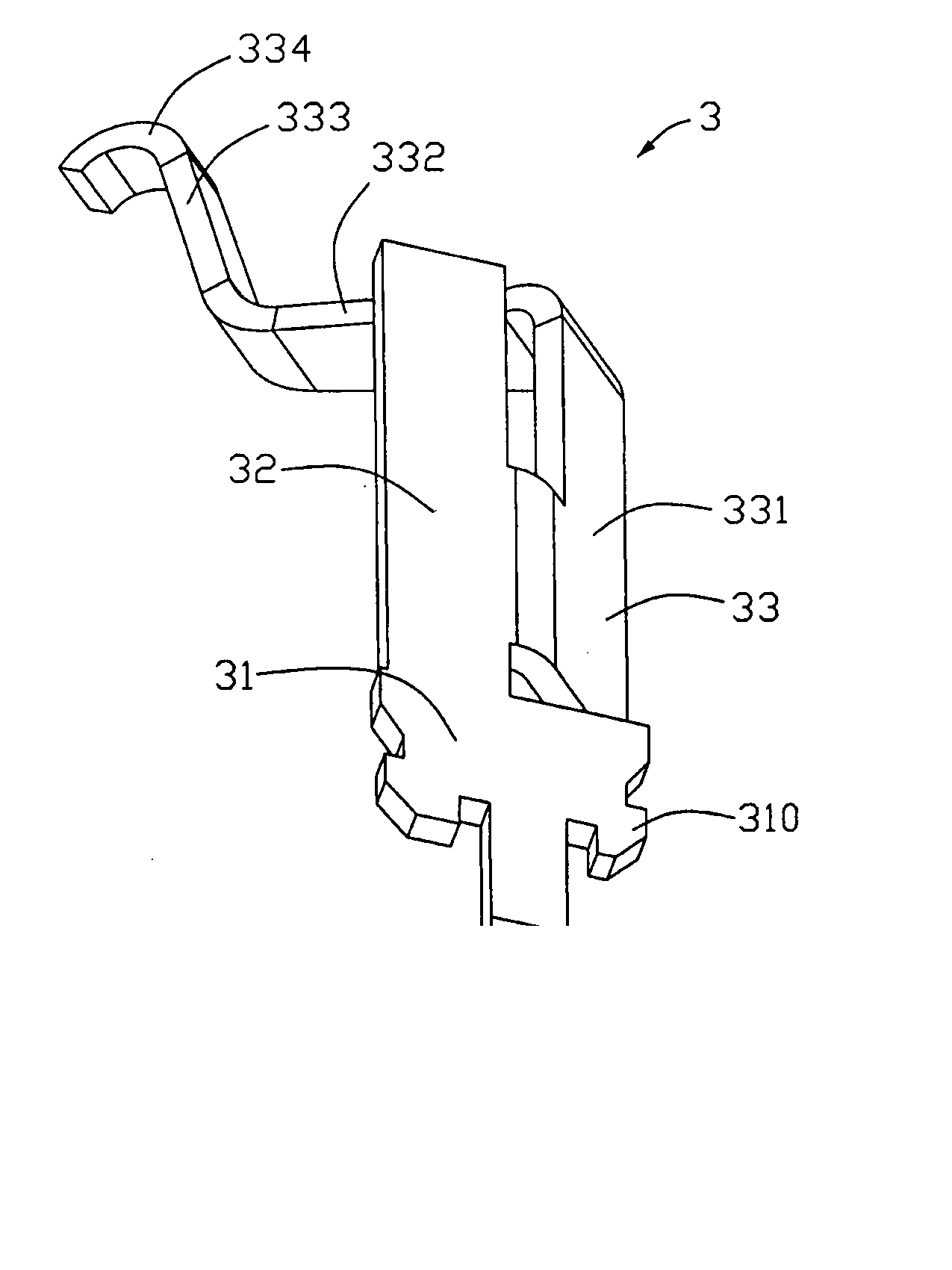
[0016]Referring also to FIGS. 3-4, the contact 3 is formed from conductive material and has a vertical plate-like retention portion 31 having a number of interfering blocks 310 at two lateral sides thereof for secur...


PUM


Abstract

A conduct (3) includes a retention portion (31), a contacting portion (334) extending upwardly from the retention portion (3), a tail portion (34) formed on a distal end of the retention portion. The tail portion (34) has a relatively larger bottom surface vertical to the major surface of the base defining a multilateral-shaped recess (340) adapted to engage a solder member, e.g. solder ball, thereby establishing electrical engagement between the contact and the PCB.

Description

BACKGROUND OF THE INVENTION[0001]1. Field of the Invention[0002]The present invention generally relates to the field of electrical connectors. And more particularly, one embodiment of the present invention relates to a conductive contact for connecting a chip module to a printed circuit board.[0003]2. General Background[0004]Electrical conductive contact are widely used in various computer systems connectors for forming electrical connection between two separate electrical interfaces, such as an electronic component and a printed circuit board. Referring to FIGS. 1-2, the conductive terminal 1 includes a vertical securing section 11, a connecting portion extending from the securing section 11, a contacting portion disposed on a top end of the connecting portion, a tail portion 13 extending from a lower end of the securing portion 32. The tail portion 13 defines a recess 130 with a circular shape on a bottom surface facing the printed circuit board for propositioning the solder ball ...

Claims


Application Information

Patent Timeline
IPC IPC(8): H01R12/14H01R12/57
CPCH01R13/2485H01R13/2442
Inventor LIAO, FANG-JUNCHEN, WEN-CHUN
Owner HON HAI PRECISION IND CO LTD
Why Eureka
Try Eureka