
Tissue grasping instrument and method for use in arthroscopic surgery

a technology of tissue grasping and arthroscopic surgery, applied in the field of instruments and methods, can solve the problem of inability to handle the anchoring force on their own

Active Publication Date: 2007-09-04
WRIGHT MEDICAL TECH
View PDF15 Cites 16 Cited by
  • Summary
  • Abstract
  • Description
  • Claims
  • Application Information

AI Technical Summary

Problems solved by technology

However, in more advanced and modern rotator cuff procedures, a graft of some type is used to fill the gap formed by the torn area or the poor tissue quality of the rotator cuff, either of which may be incapable of handling anchoring forces on their own.

Method used


Image

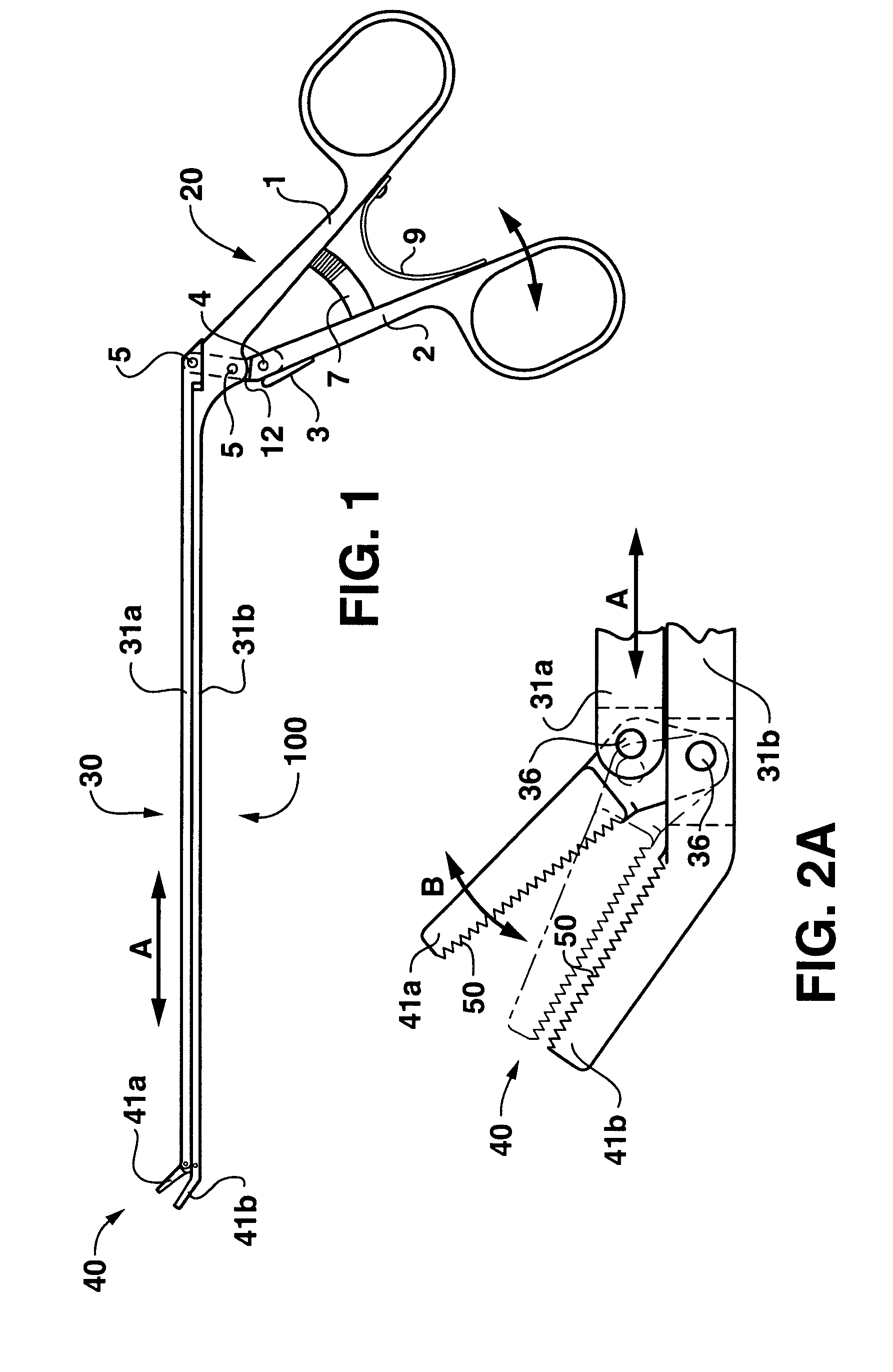
  • Tissue grasping instrument and method for use in arthroscopic surgery
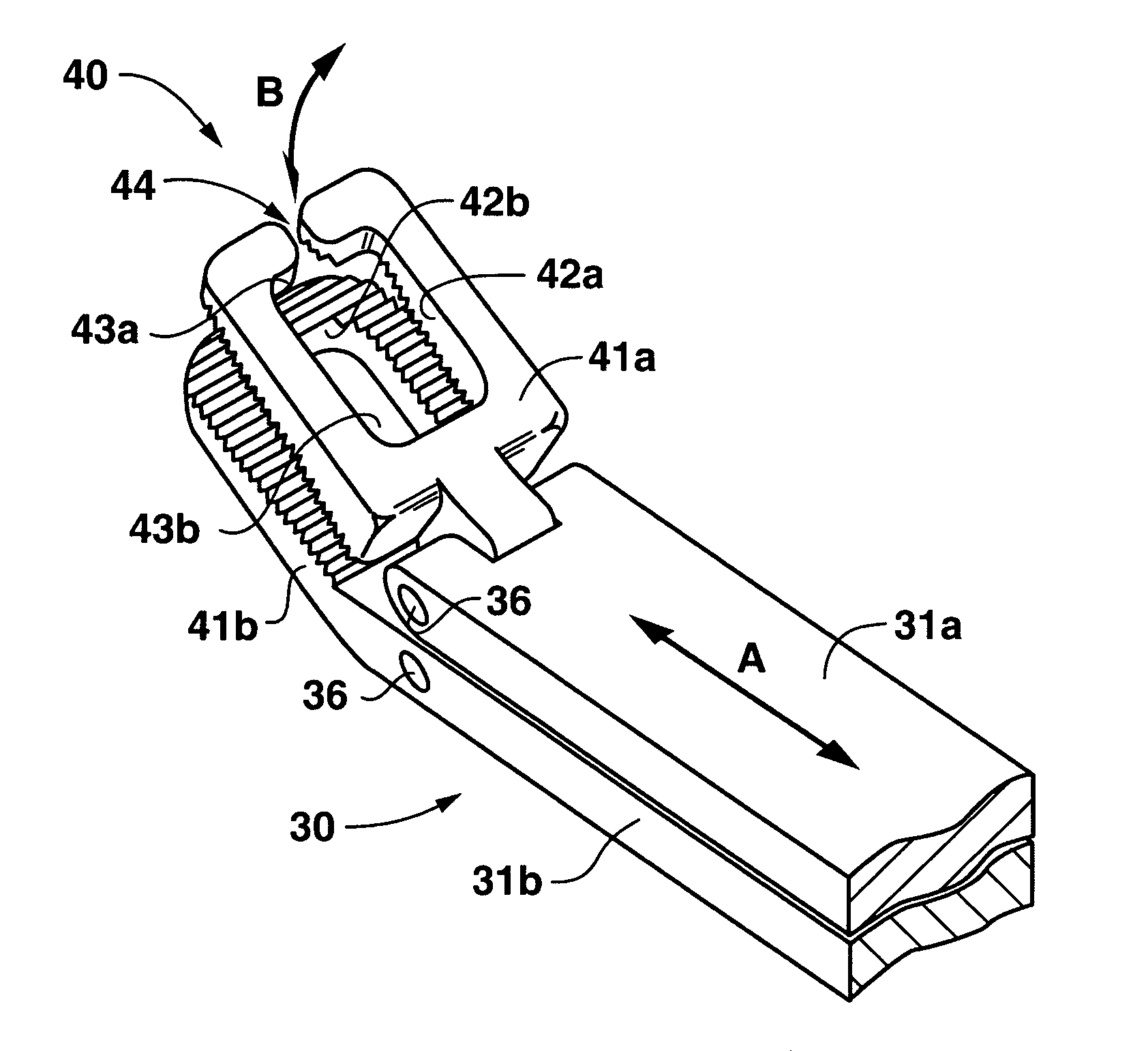
  • Tissue grasping instrument and method for use in arthroscopic surgery
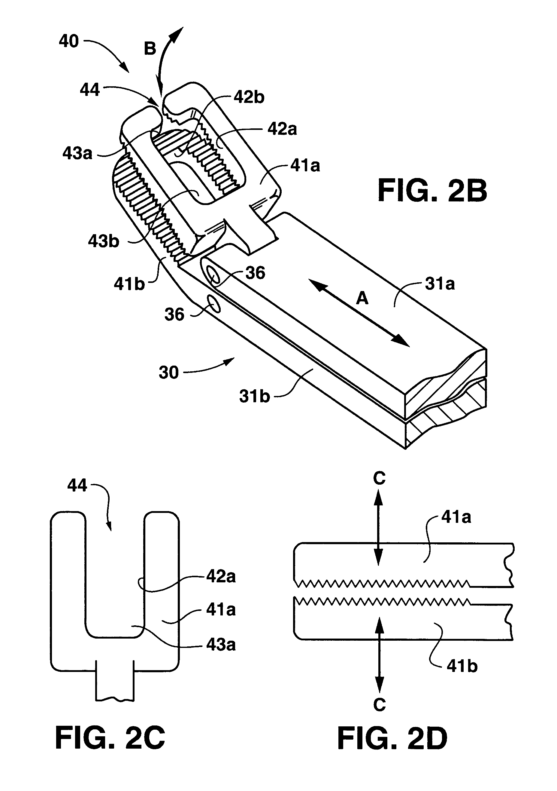
  • Tissue grasping instrument and method for use in arthroscopic surgery

Examples


Embodiment Construction

[0020]FIG. 1 depicts an exemplary embodiment of a tissue grasping instrument 100 according to the invention.

[0021]Tissue grasping instrument 100 generally comprises a handle portion 20, a body portion 30, and a jaw portion 40.

[0022]Jaw portion 40 comprises first and second jaws 41a, 41b. As shown by arrow B in FIGS. 2A and 2B, first and second jaws 41a, 41b are designed to move with respect to each other, preferably, but not absolutely, as described as follows. Second jaw 41b is at least integral, and preferably unitary (for ease of construction) with second elongated body portion 31b. First jaw 41a is pivotally mounted to both of the first and second elongated body portions 31a, 31b, by any suitable mechanism, preferably pivot pins 36 as shown. Accordingly, as the elongated body portions 31a, 31b linearly move with respect to each other, e.g., first elongated body member 31a moves in the direction of arrow A, the first jaw 41a is caused to pivot in the direction of arrow B. This me...


PUM


Abstract

A tissue grasping instrument and method for use in arthroscopic surgery is disclosed. Typically, the instrument will be used in the manipulation of sutures and a graft in the form of an acellular matrix during the repair of rotator cuffs.

Description

FIELD OF THE INVENTION[0001]This invention generally concerns instrumentation and methods useful in the field of arthroscopic surgery. The invention specifically concerns instrumentation and methods useful in handling and stitching tissues and tissue grafts during arthroscopic rotator cuff repair surgery.BACKGROUND OF THE INVENTION[0002]In the field of arthroscopic surgery, typically proper instrumentation can is important to a successful procedure. Accordingly, a large number of specialized instruments have been developed, some with very fine differences from existing instruments, mainly to meet specific needs or doctor preferences. For example, some instruments, such as U.S. Pat. No. 5,947,982, incorporated entirely herein by reference, only pass sutures and do not grasp tissue. In general, the needs of arthroscopic or “closed” surgery are discussed in U.S. Pat. No. 5,843,100, whose contents are also entirely incorporated herein by reference.[0003]U.S. Pat. No. 5,575,801, issued N...

Claims


Application Information

Patent Timeline
Patent Type & Authority Patents(United States)
IPC IPC(8): A61B17/04A61B17/28
CPCA61B17/29A61B17/0469A61B2017/2902A61B2017/294
Inventor HARRIS, JR., BRIAN R.SNYDER, STEPHEN J.
Owner WRIGHT MEDICAL TECH
Learn More