Forceps for performing endoscopic or arthroscopic surgery

a technology for arthroscopic surgery and forceps, applied in the field of forceps, can solve the problems of high cost, complex management, direct added cost, lack of flexibility among instruments,

Inactive Publication Date: 2006-11-16
LIVNEH STEVE
View PDF9 Cites 41 Cited by
  • Summary
  • Abstract
  • Description
  • Claims
  • Application Information

AI Technical Summary

Problems solved by technology

Managing and maintaining this inventory is costly and complex.
Lack of flexibility among the instruments are a direct added cost to each surgery, while maintaining the different variety of instruments necessitates trained personnel and sterilization facilities and capabilities.

Method used


Image

  • Forceps for performing endoscopic or arthroscopic surgery
  • Forceps for performing endoscopic or arthroscopic surgery
  • Forceps for performing endoscopic or arthroscopic surgery

Examples


Embodiment Construction

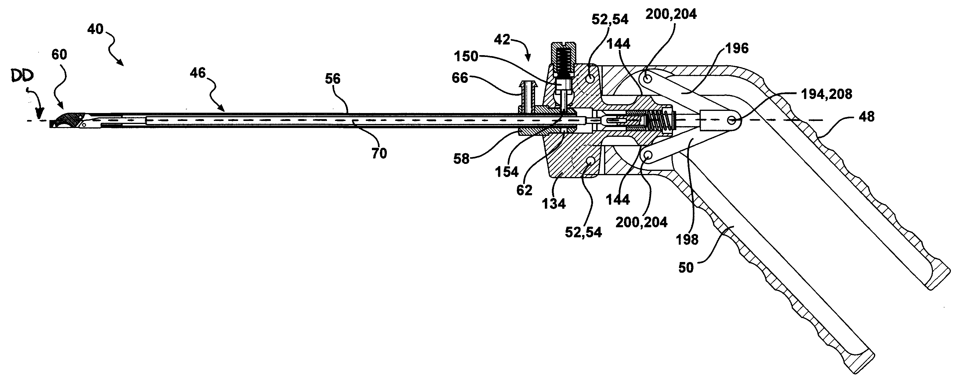
[0044] Referring to the Figures, wherein like numerals indicate like parts throughout the several views, forceps are generally shown at 40. Forceps 40 are used for performing various procedures during endoscopic or laparoscopic types of surgery. A common type of procedure is cutting. However, they can be used to perform other types of procedures such as grasping, manipulating, or ablating, for example.

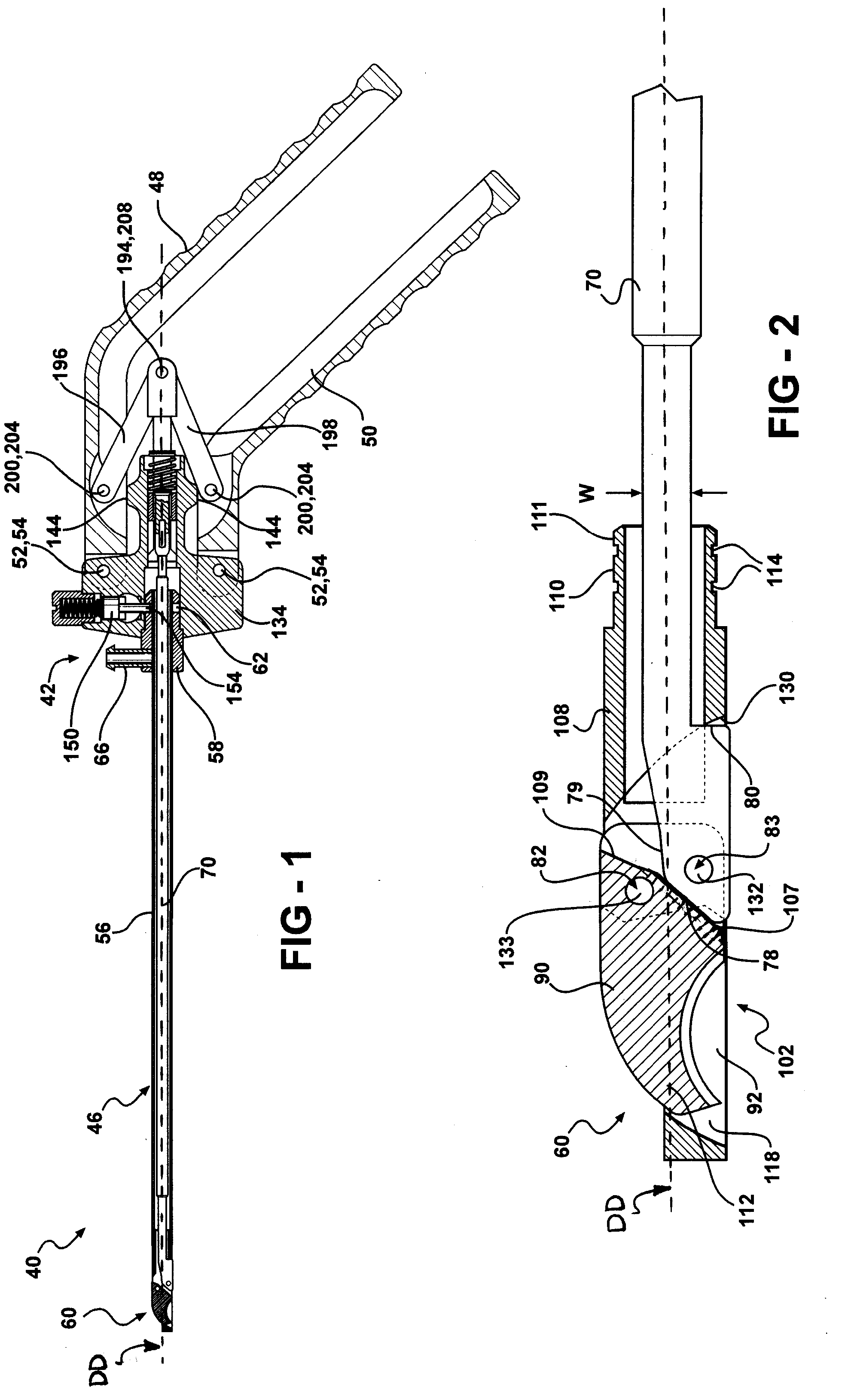
[0045] The forceps 40 include a body assembly 42, a tube assembly 46, and a pair of opposing handles 48, 50. The handles 48, 50 include an upper handle 48 and a lower handle 50. The handles 48, 50 are pivotally connected to the body assembly 42. A handle screw 52 attaches each handle to the body assembly 42 but allows the handles 48, 50 to pivot. Teflon washers 54 may be interposed between each of the handles 48, 50 and the body assembly 42 for reducing friction when pivoting each handle 48, 50 with respect to the body assembly 42.

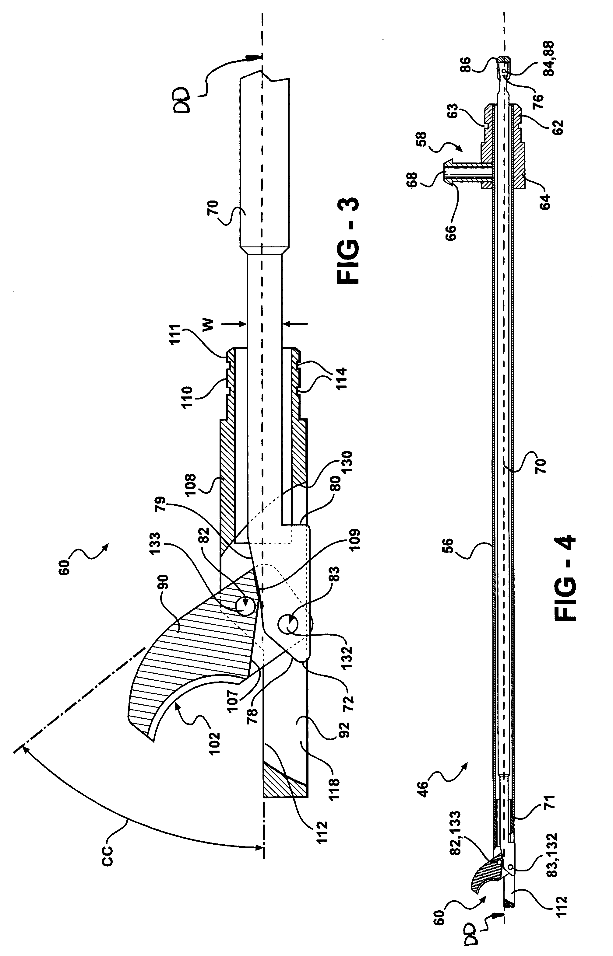
[0046] The tube assembly 46, shown in FIG. 4, include...


PUM


Abstract

Forceps for performing endoscopic or arthroscopic surgery include a body assembly, a tube assembly, and a pair of handles that pivot with respect to the body. The tube assembly is removably attached to the body assembly. The tube assembly includes a hollow tube and a tip assembly. The tip assembly includes an electrode or a blade for performing the surgery. The tip assembly and the blade are connected to the body and the handles by a cable. As the handles pivot, the cable slides within the tube to move the blade. When a different tube assembly (i.e., a bipolar or a monopolar electrode) or another style of tip assembly are desired, the installed one is removed and replaced by a new tube assembly or tip assembly as desired.

Description

CROSS REFERENCE TO RELATED APPLICATION [0001] This application claims the benefit of U.S. Provisional Patent Application Ser. Nos. 60 / 676,645 and 60 / 717,074, which are hereby incorporated by reference.BACKGROUND OF THE INVENTION [0002] Today's endoscopic and arthroscopic surgical instruments encompass a multitude of different designs. While all may be designed to serve the same function, for example, each one may be shaped differently to provide the surgeon better access to perform the procedure. For example, a pair of forceps may include a tube that extends from a pair of handles. A blade is disposed at an end to the tube for performing the surgery. The tube, near the blade in one pair of forceps is bent upward to provide the surgeon with the required access in the patient to make a first cut. However, if the surgeon needs to perform a second cut, on the same patient, but in a different position, the surgeon must get a different pair of forceps where the tube is bent to a different...

Claims


Application Information

Patent Timeline
Patent Type & Authority Applications(United States)
IPC IPC(8): A61B17/00
CPCA61B17/1608A61B2218/007A61B18/1442A61B2017/00137A61B2017/00473A61B2017/2902A61B2017/2913A61B2017/2919A61B2017/292A61B2017/2933A61B2017/2946A61B2017/347A61B2019/304A61B2019/305A61B17/2909A61B2090/034A61B2090/035
Inventor LIVNEH, STEVE
Owner LIVNEH STEVE
Why Eureka
Try Eureka