

Circular bone tunneling device
- Summary
- Abstract
- Description
- Claims
- Application Information
AI Technical Summary
Benefits of technology
Problems solved by technology
Method used
Image


Examples
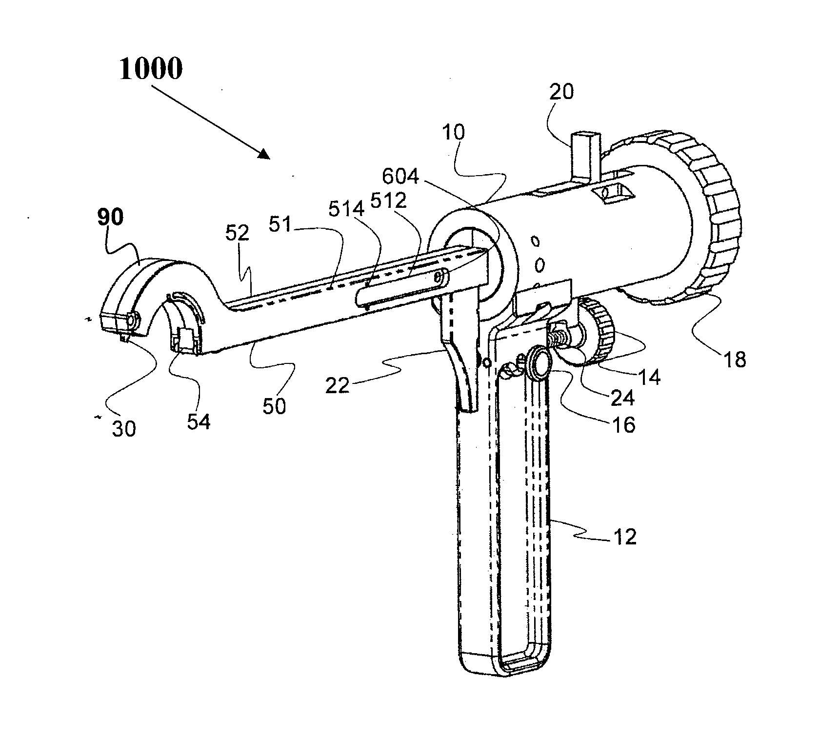
embodiment 1000
[0139]Reference is now made to FIG. 113, which provides an isometric view of embodiment 1000 after the left-hand side of the body 51 has been removed to reveal the interior of the hollow body. In this embodiment, the driving mechanism for the rigid circular hollow tube comprises a series of slidable members (beads) attached to one another. The interior of the body includes on its upper or lower side or both a track 522 that guides the movement of the slidable members. The distal slidable member 4 is flat on its forward side, which engages the proximal end of the hollow tube. The remaining slidable members 2 need not be flat on the forward side; as described in detail below, in preferred embodiments, they present a substantially circular profile. In this embodiment, the driving mechanism also includes at its proximal end rigid circular hollow tube actuator 6 that engages the rigid circular hollow tube control such that when the rigid circular hollow tube control moves forward, it cau...
second embodiment
[0187]FIG. 10 also shows the support element driving mechanism. In this embodiment, the support element driving mechanism comprises an actuator 58 that engages at its proximal end the support element control and that is pivotably connected substantially at its distal end to a yoke 340 via a pin (not shown in FIG. 10). Yoke 340 is pivotably connected substantially at its distal end to the support element. When the support element control is engaged, actuator 58 travels distally, whereby yoke 340 moves downward, causing the support element to extend. In the embodiment shown in FIG. 10, handle 12 comprises two portions, a movable distal portion 12A and a stationary proximal portion 12B. In the embodiment shown, the handle is designed such that the user can grip it by placing his or her fingers through orifices at the bottom of the two portions of the handle. The movable distal portion of the handle further comprises a tab that fits into a slot in the underside of shaft 50.
[0188]In this...
embodiment 3000
[0195]The slider is attached to the hollow elongate body of the circular tunneler / suture passer such that it can slide back and forth along the body. For example, it can comprise a channel with internal dimensions chosen to provide a slip fit over the body. Manipulator 820 is attached to the proximal side of the slider and sits on the upper side of the body. As can be seen in the diagram, in preferred embodiments, the manipulator has an ergonomic shape such that it can be pushed and pulled by the thumb of the operator of the device. Grasping member 800 is attached to the distal side of the slider. It is disposed on the upper side of the elongate body and slides along the distal-proximal axis of the body on the upper side of the body and passes under the head at the point at which the head is attached to the body. As can be seen in the diagram, in preferred embodiments, it has an elongated shape (e.g. a parallelepiped that is wider than it is high) and has a length sufficient that wh...
PUM
 Abstract
Description
Claims
Application Information