Next high frequency improvement using hybrid substrates of two materials with different dielectric constant frequency slopes

a dielectric constant frequency slope and hybrid substrate technology, applied in the direction of cross-talk/noise/interference reduction, coupling device connection, contact member penetrating/cutting insulation/cable strand, etc., can solve the problem of deteriorating limit lines, high frequency margin further deterioration, cross-talk is a common problem, etc. problem, to achieve the effect of reducing the next in the connector, and improving the next high frequency performan

Active Publication Date: 2007-09-04
COMMSCOPE INC
View PDF40 Cites 75 Cited by
  • Summary
  • Abstract
  • Description
  • Claims
  • Application Information

AI Technical Summary

Benefits of technology

[0011]The present invention overcomes the problems and limitations of the related art techniques of reducing NEXT in connectors. Particularly, the present invention provides an apparatus and method that simultaneously improves the NEXT high frequency performance when low crosstalk plugs are used, and the NEXT low frequency performance when high crosstalk plugs are used, by making different substrates of a multi-stage compensation system in materials having different dielectric frequency characteristics. Accordingly, the present invention improves both the low frequency (e.g., 1–100 MHz) crosstalk performance and the high frequency (e.g., 250–500 MHz; or 500 MHz and greater) crosstalk performance of modular outlets and panels.

Problems solved by technology

Crosstalk is a common problem in communication devices using connectors.
Although effective, the NEXT compensating scheme of the '358 patent suffers a drawback in that the NEXT margin relative to the Telecommunications Industry Association (TIA) limit line deteriorates at low frequency (below approximately 100 MHz) when a high crosstalk plug is used with the jack, and at high frequency (beyond approximately 250 MHz) when a low crosstalk plug is used with the jack.
Thus, while the low frequency margin (low frequency performance of the connector), when a high crosstalk plug is used with the jack, can be improved by increasing the compensation level, such an action would lead to further deterioration of the high frequency margin (high frequency performance of the connector) when a low crosstalk plug is used with the jack.
Conversely, while the high frequency margin, when a low crosstalk plug is used with the jack, can be improved by decreasing the compensation level, such an action would lead to further deterioration of the low frequency margin when a high crosstalk plug is used with the jack.

Method used


Image

  • Next high frequency improvement using hybrid substrates of two materials with different dielectric constant frequency slopes
  • Next high frequency improvement using hybrid substrates of two materials with different dielectric constant frequency slopes
  • Next high frequency improvement using hybrid substrates of two materials with different dielectric constant frequency slopes

Examples


first embodiment

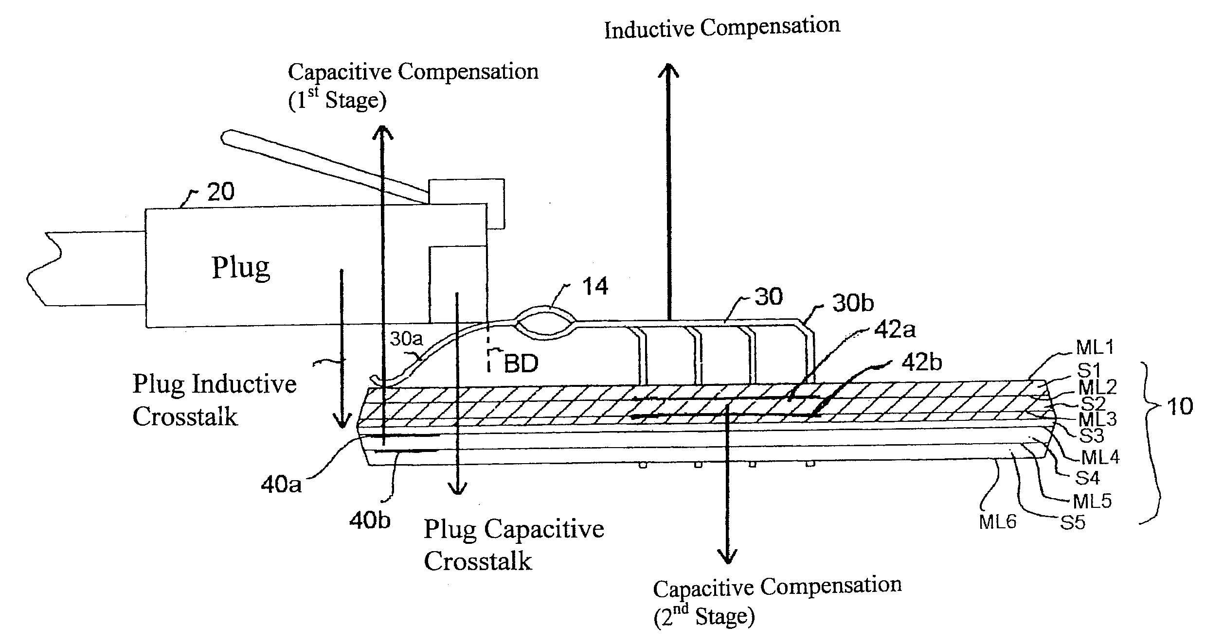
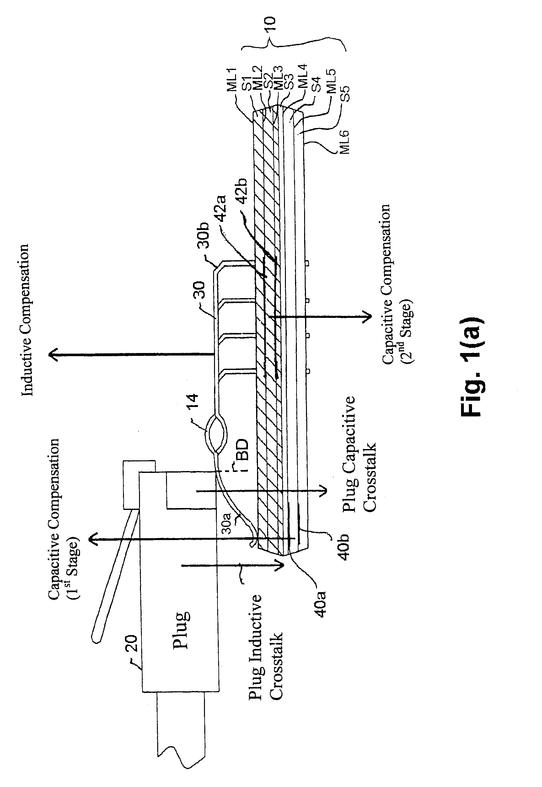
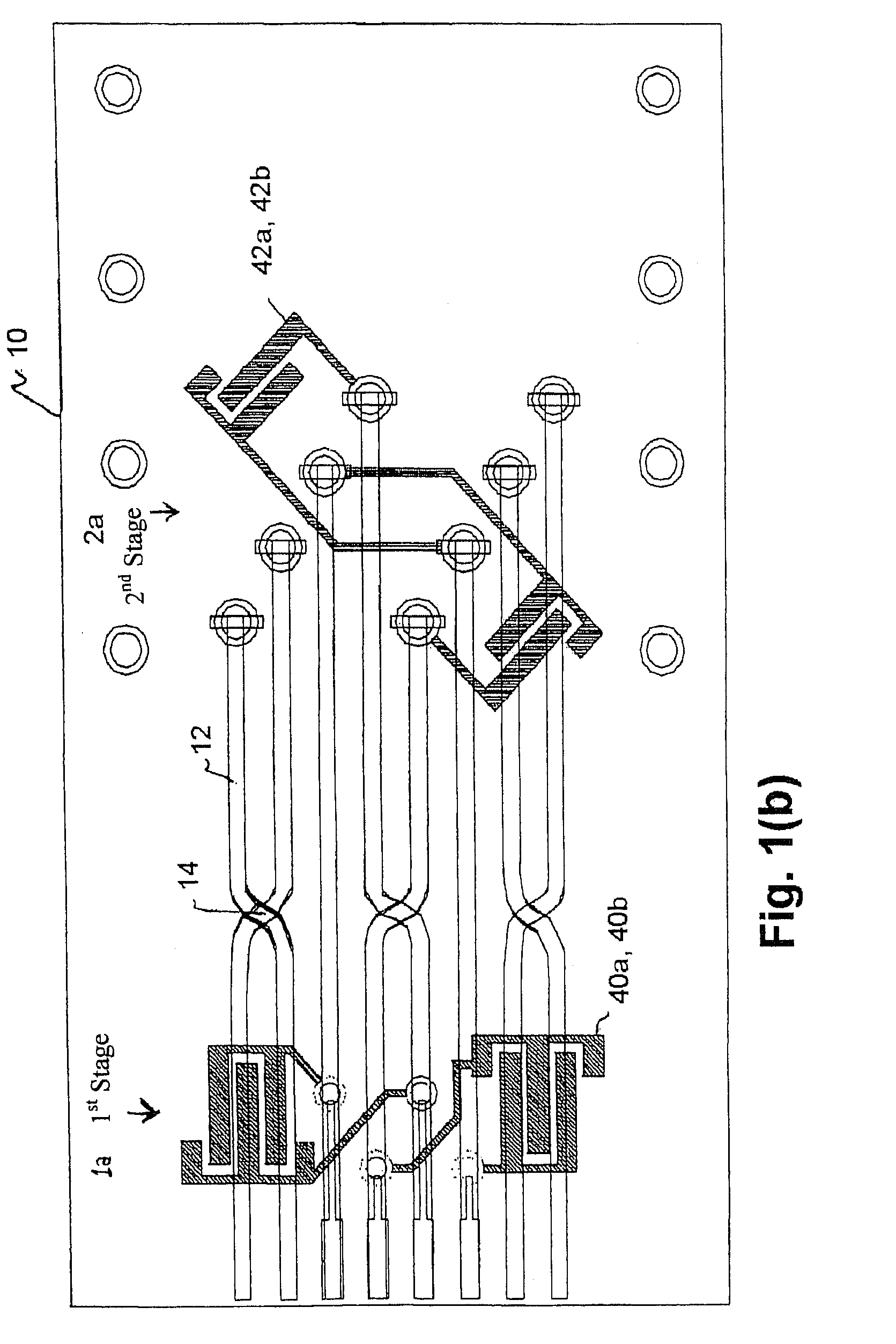
[0023]FIG. 1(a) is a side view of a connector and FIG. 1(b) is a top plan view of the printed circuit board and compensation capacitors of FIG. 1(a), all according to the present invention.

[0024]Referring to FIGS. 1(a) and 1(b), the connector includes contacts 30 having crossovers 14, and a hybrid PCB 10, where a plug 20 is to mate with the connector. The plug 20 can be a modular plug such as one used at the end of a phone line or a patch cord used to connect a personal computer to a wall outlet. The contacts 30 can be soldered or press-fitted into plated-through holes located at the appropriate portions of the PCB 10 and can be spring wire contacts. Moreover, the contacts 30 have a current carrying portion 30b and a non-current carrying portion 30a, where a boundary BD between these portions 30a and 30b are indicated in FIG. 1(a). The contacts 30 and the PCB 10 can be housed in a housing such as a modular jack, so that when the plug 20 enters the jack, the electrical contacts on th...

third embodiment

[0036]Particularly, referring to FIG. 3(a), the PCB 50 is composed of four substrates S1–S4 and five metalized layers ML1–ML5, which are alternatingly stacked up. All the four substrates S1–S4 are made of a high DK material. The contacts 30 on the first metalized layer ML1 are not shown in FIG. 3(a), but are shown in FIG. 3(b) as the wire pairs 12 having the cross-overs 14.

[0037]Referring to FIG. 3(b), at the first stage, parallel plate capacitors 60a and 60b are respectively formed on or as part of the second and third metalized layers ML2 and ML3, where the two plates 60a and 60b of each capacitor parallel each other. At the second stage, surface mount capacitors 62a and 62b are mounted on the first metalized layer ML1 (or under the last metalized layer).

[0038]In this embodiment, the magnitude of the first stage capacitive coupling declines with frequency because the first stage parallel plate capacitors 60a and 60b reside in the PCB 50, which has a high DK slope. The second stag...

fourth embodiment

[0039]FIG. 4(a) is a side view of printed circuit boards of a connector and FIG. 4(b) is a top plan view of the printed circuit boards and compensation capacitors of FIG. 4(a), all according to the present invention.

[0040]The fourth embodiment is similar to the first embodiment in that the connector includes the contacts 30 and receives a plug such as the plug 20. However, instead of using one hybrid PCB 10 made of high and low DK materials as in the first embodiment, in the fourth embodiment two homogenous PCBs are provided in the connector, where all the substrates of the first PCB are made of a high slope DK material and all the substrates of the second PCB are made of a low slope DK material.

[0041]Particularly, referring to FIG. 4(a), in the fourth embodiment, the first PCB 70 is composed of four substrates S1–S4 and five metalized layers ML1–ML5, which are alternatingly stacked up. All the four substrates S1–S4 in the first PCB 70 are made of a high slope DK material. The secon...


PUM


Abstract

A connector is provided for simultaneously improving both the NEXT high frequency performance when low crosstalk plugs are used and the NEXT low frequency performance when high crosstalk plugs are used. The connector includes PCB substrates made of materials having different dielectric frequency characteristics.

Description

[0001]The present application claims the priority benefit of U.S. Provisional Application No. 60 / 456,236 filed on Mar. 21, 2003, the entire contents of which are herein fully incorporated by reference.BACKGROUND OF THE INVENTION[0002]1. Field of the Invention[0003]The present invention relates to near-end crosstalk (NEXT) compensation in communication connectors and, more particularly, to a technique of canceling or reducing NEXT utilizing substrates such as printed circuit boards (PCBs) composed of different dielectric constant materials.[0004]2. Discussion of the Related Art[0005]Noise or signal interference between conductors in a connector is known as crosstalk. Crosstalk is a common problem in communication devices using connectors. Particularly, in a communication system where a modular plug often used with a computer is to mate with a modular jack, the electrical wires (conductors) within the jack and / or plug produce near-end crosstalk (NEXT), i.e., a crosstalk over closely-p...

Claims


Application Information

Patent Timeline
Patent Type & Authority Patents(United States)
IPC IPC(8): H05K1/00H05K1/02H05K1/16
CPCH05K1/0228H05K1/162H01R13/6466H05K1/0231H05K1/0298H05K3/4688H05K2201/09236H05K2201/09245H05K2201/09672H05K2201/10189H01R13/6464H01R24/00
Inventor ADRIAENSSENS, LUCHASHIM, AMIDLONG, TROY
Owner COMMSCOPE INC
Why Eureka
Try Eureka