Tool support for lathes

a tool and lathe technology, applied in the field of tools, can solve the problems of high secondary processing time and time-consuming operation, and achieve the effects of reducing the secondary processing time for tool selection, and facilitating the selection of tools

Inactive Publication Date: 2007-09-11
MICROSWISS TECH
View PDF15 Cites 20 Cited by
  • Summary
  • Abstract
  • Description
  • Claims
  • Application Information

AI Technical Summary

Benefits of technology

[0006]According to the invention, the tool support enables holding two different tools and selective use of the tools, keeping the cost of the constructive elements of the support and their number at a minimum, particularly when a single motor is used for moving the components of the support, wherein a drive shaft for displacing the slide and selectively the desired tool support. This is provided by the intermediary of a lever having an inner control curve or two cam discs.
[0007]The forced sequence of movement is made in a controlled manner, sequentially or simultaneously along the trajectory axis X and Y or by a translatory path. This ensures that the secondary processing time for the selection of a

Problems solved by technology

This operation is often very time co

Method used


Image

  • Tool support for lathes
  • Tool support for lathes
  • Tool support for lathes

Examples


Embodiment Construction

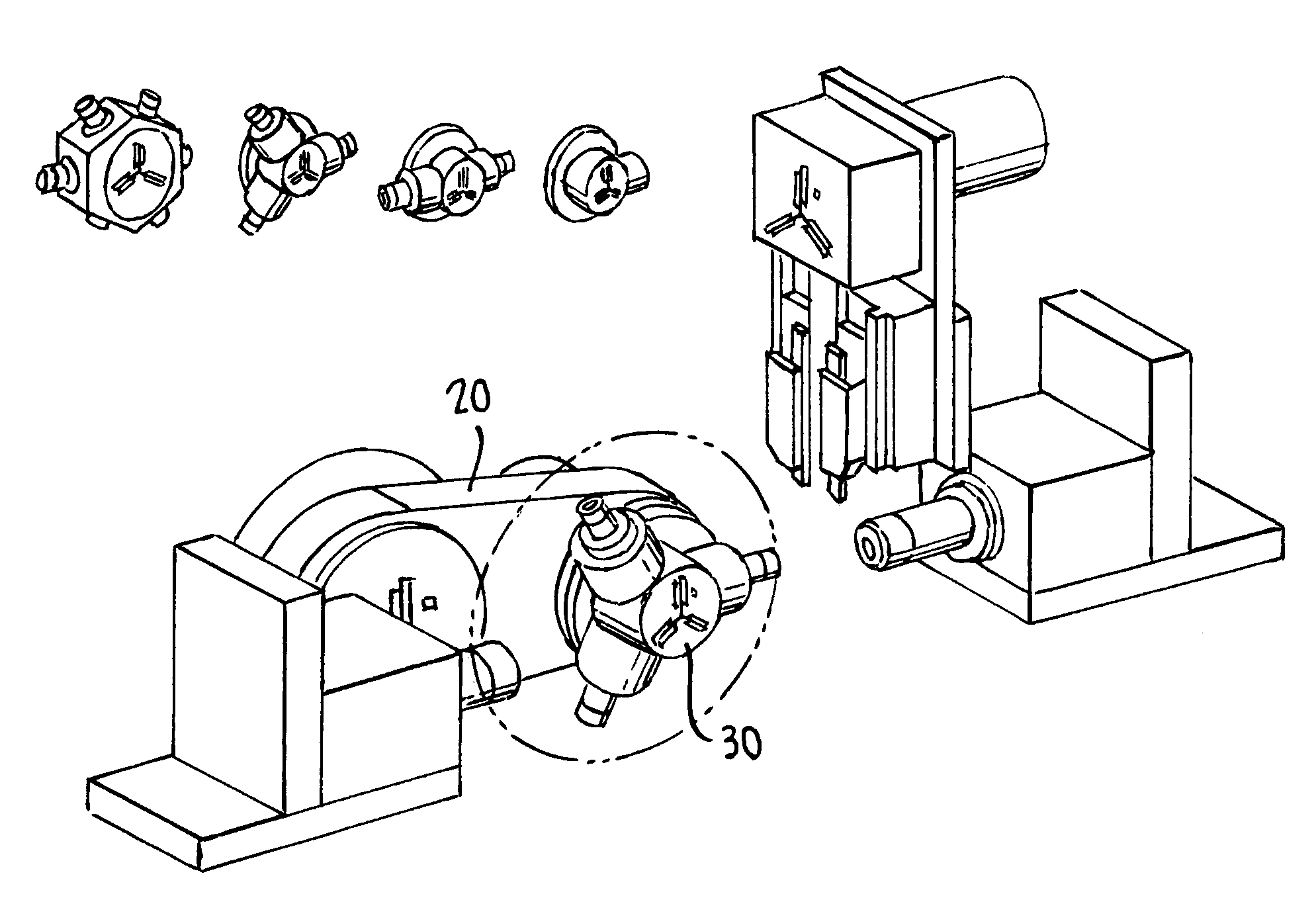
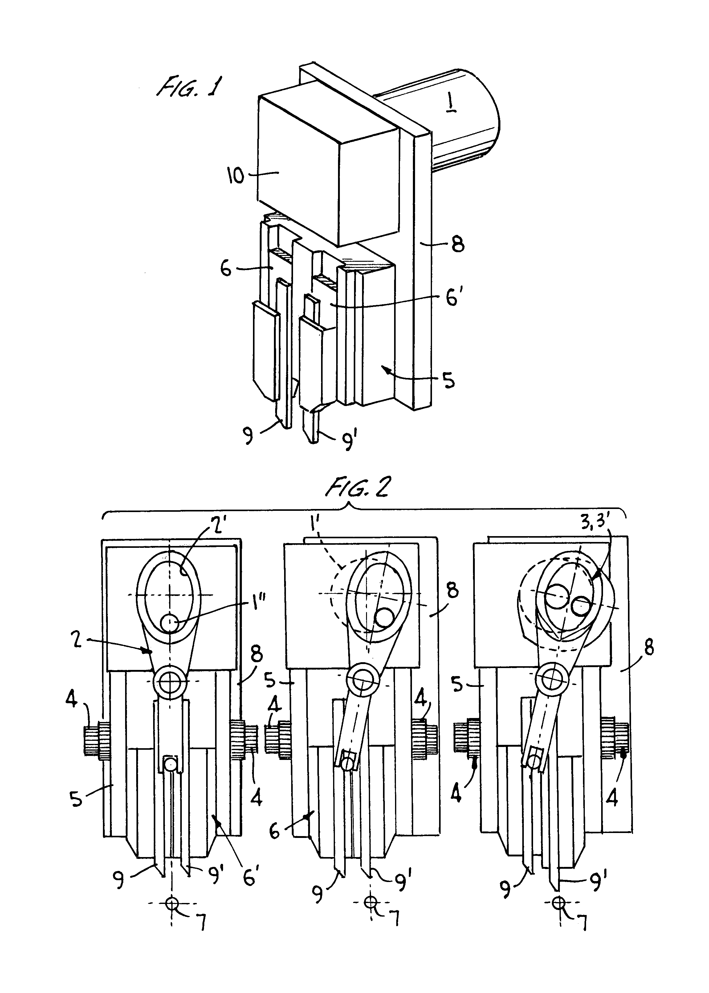
[0017]FIG. 1 shows schematically a tool support, in accordance with the invention, having a central drive motor 1 and a base structure 8, on which a laterally displaceable slide 5 with two tool holders 6,6′, is arranged. Different tools 9,9′ are held in the holders 6,6′. Behind the cover 10, which is connected to the slide 5 and which is displaceable, is arranged drive control elements 2 and 3,3′ (see FIG. 2).

[0018]The base plate 8 is usually mounted on a Z-slide (not shown), thus allowing an additional controlled movement in the Z-direction (along the spindle).

[0019]Due to the additional Z-movements, further simultaneous work operations are possible which permit, particularly for turning automats, a massive increase in productivity.

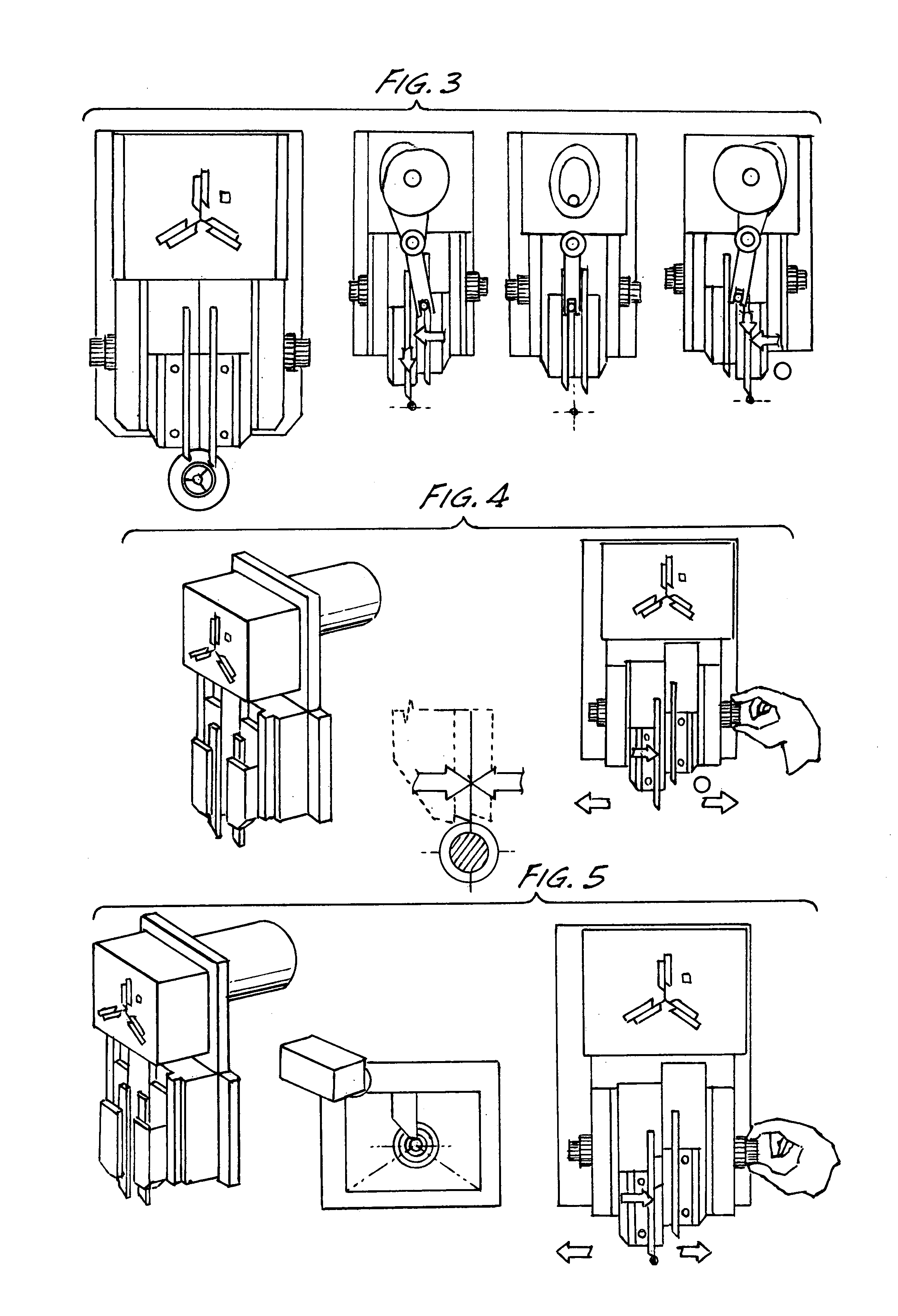
[0020]FIG. 2 illustrates schematically the operation principle of the double or twin tool support.

[0021]Motor 1 is driven by the intermediary of shaft 1′ and the control elements, namely lever 2 and cam 3. The lever 2 with inner curve 2′ serves to displa...


PUM

PropertyMeasurementUnit
Angleaaaaaaaaaa
Angleaaaaaaaaaa
Angleaaaaaaaaaa

Abstract

The tool support comprises a basic structure (8) on which a slide (5) is movable in a controlled manner transversely to the spindle axis (7), two tool holders (6) being mounted on said slide which are displaceable parallel to each other and serving to hold different tools (9,9′), said holders (6,6′) being selectively displaceable in the direction of the spindle axis (7) or away from that axis through an angle of 90° with respect to the direction of movement of the slide (5), and further comprising driving means (1,2,3,3′) to displace the slide (5) and the tool holders (6,6′) along their axis of movement (Y,Z) into a predetermined working position.

Description

FIELD OF INVENTION[0001]The present invention relates to a tool support for a work piece at the working spindle of a lathe.BACKGROUND OF THE INVENTION[0002]Tool supports for tools to be mounted on the working spindle of a lathe are known and are useful for machining work pieces of any kind of material. Depending on the work to be performed, appropriate tools have to be chosen and mounted on the tool support. This operation is often very time consuming (secondary processing time). In order to avoid this very complicated process, complex turret heads with different tools are used.BRIEF SUMMARY OF THE INVENTION[0003]An object of the present invention is to provide a tool support having high precision with a very simple construction and which reduces the secondary processing time (re-tooling) practically to zero.[0004]This object is achieved with a tool support of the type defined herein.[0005]Particularly advantageous embodiments of the invention are defined in the claims.[0006]Accordi...

Claims


Application Information

Patent Timeline
IPC IPC(8): B23B3/00B23C1/00B23B29/32B23Q1/54
CPCB23B29/323B23Q1/5418Y10T82/2543Y10T82/2508Y10T29/5173Y10T82/16591Y10T82/192Y10T82/2587
Inventor UEBELHART, BAUDOIN ERNEST
Owner MICROSWISS TECH
Why Eureka
Try Eureka