Auto tensioner

a technology of auto tensioner and guide plate, which is applied in the direction of belt/chain/gearing, mechanical equipment, belt/chain/gearing, etc., can solve the problems of generating secondary noise or the like, generating unusual sound or noise in the auto tensioner, and not getting the effect of merely increasing the thickness of the guide pla

Active Publication Date: 2007-09-11
JTEKT CORP
View PDF21 Cites 8 Cited by
  • Summary
  • Abstract
  • Description
  • Claims
  • Application Information

AI Technical Summary

Problems solved by technology

The generation of the stick-slip phenomenon causes the guide plate made of steel plate to vibrate, which results in generation of an unusual sound or noise in the auto tensioner.
However, materials of high rigidity such as a steel plate or the like have disadvantages of poor attenuation of a vibration and a natural resonance caused by the vibration, thereby generating a secondary noise or the like.
Therefore, in terms of controlling the vibration of the guide plate due to the stick-slip and the consequent reduction of the unusual sound and noise in the auto tensioner, there can be no good results expected from merely increasing the thickness of the guide plate.
Further, to increase the thickness is not preferable leading to an increased weight of the auto tensioner.

Method used


Image

  • Auto tensioner
  • Auto tensioner
  • Auto tensioner

Examples


Embodiment Construction

[0025]Referring to FIGS. 1 through 9, an auto tensioner according to the best mode for executing the present invention is hereinafter described.

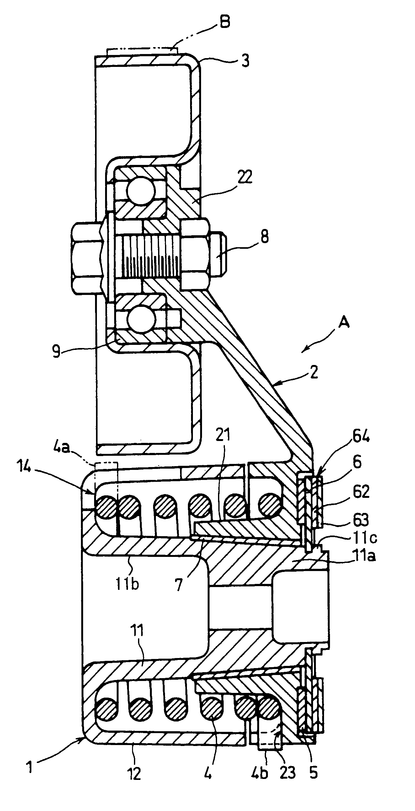
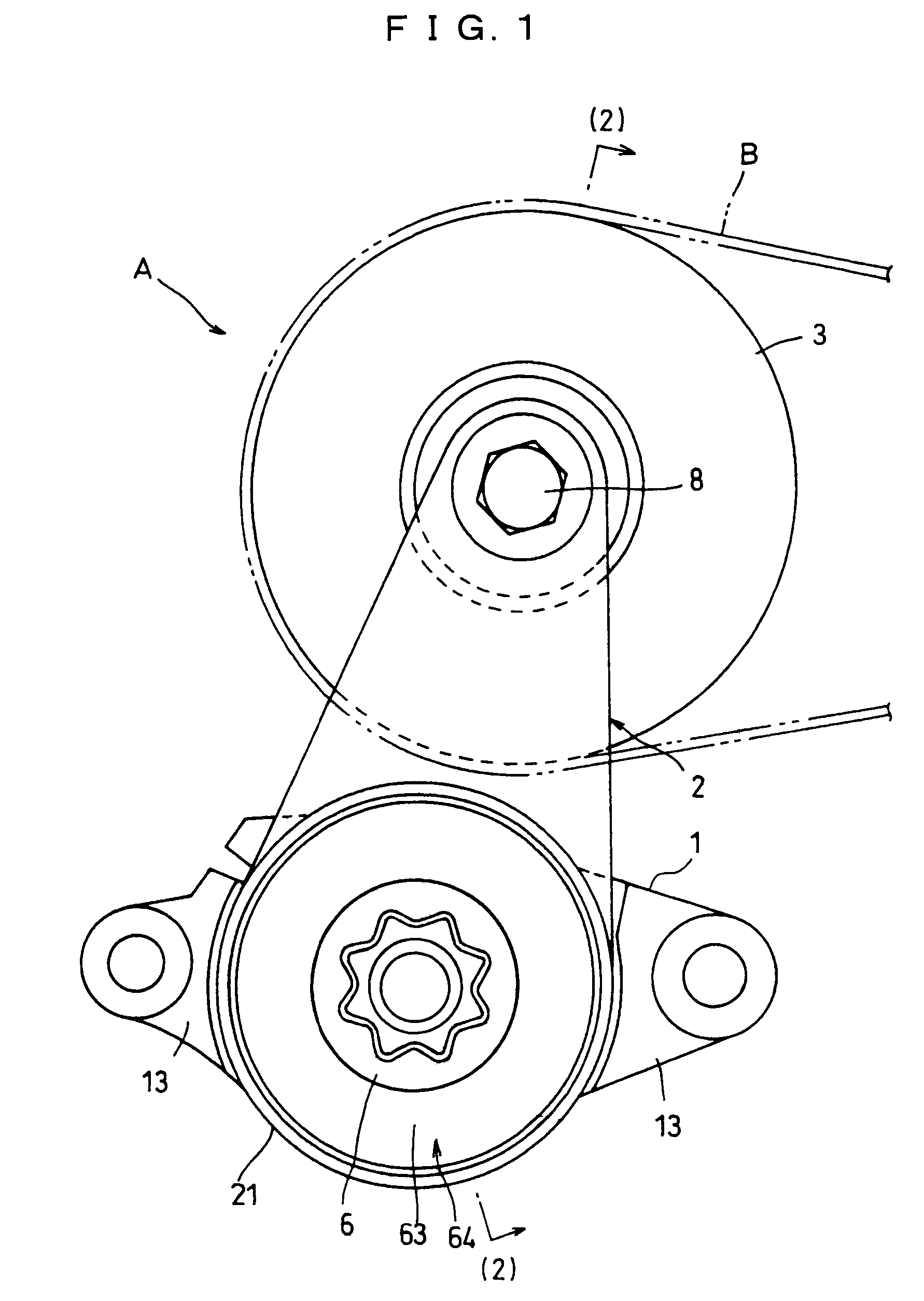
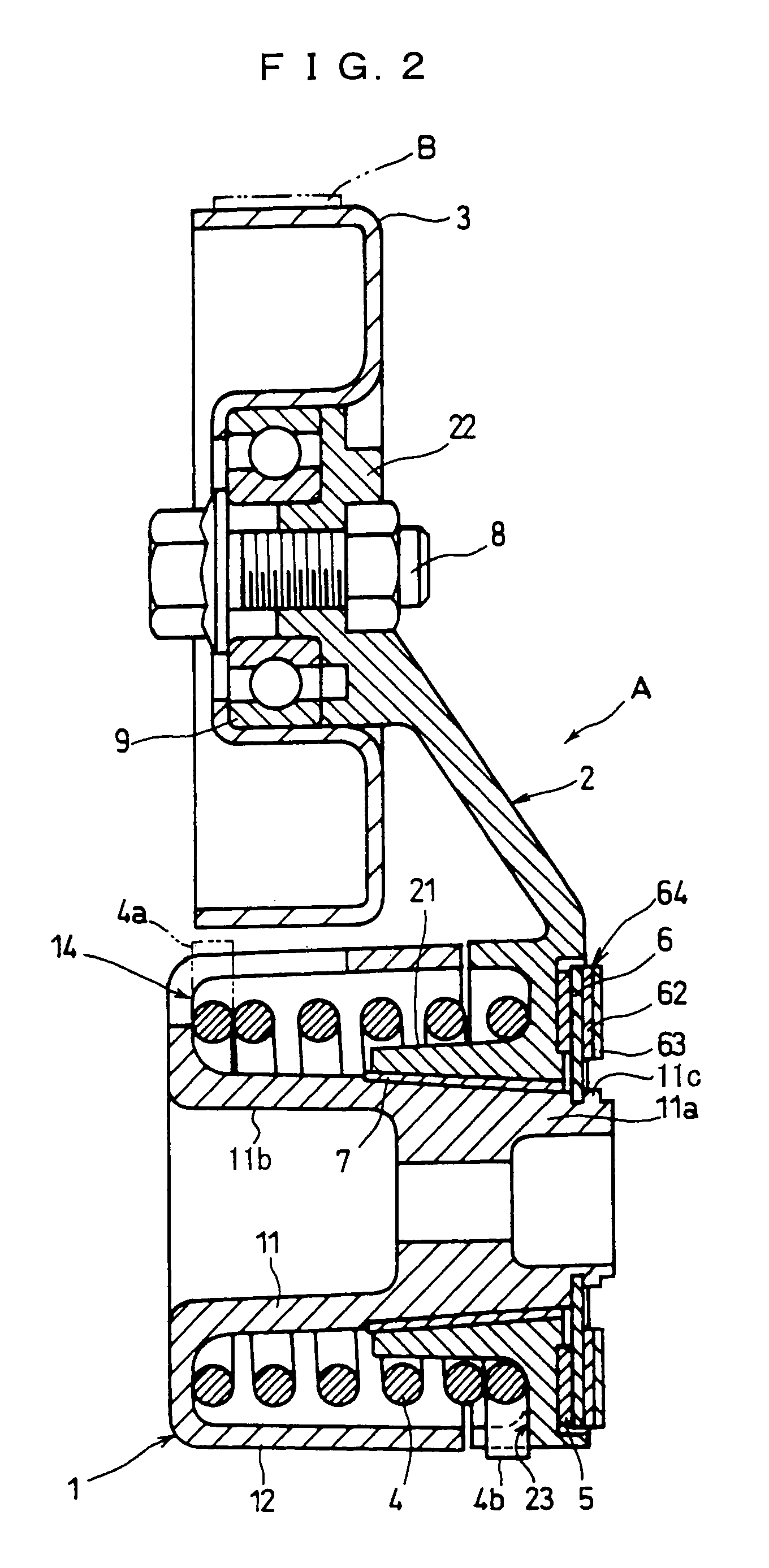
[0026]In these figures, an auto tensioner A comprises a support member 1, a tension arm 2, a tension pulley 3, a helical torsion coil spring 4, a friction plate 5, a guide plate 6 and a bushing 7 as a slide bearing. A belt B is wound around the outer periphery of the tension pulley 3.

[0027]The auto tensioner A, while allowing the movement of the tension pulley 3 in response to the tensile force variations of the belt B, regulates the movement of the tension pulley 3 so that the vibration and impact from the belt B are attenuated. When the tensile force of the belt B decreases by slow degrees, the arm 2 and the tension pulley 3 are tilted to the left side in FIG. 1 by the torsion restoring force of the helical torsion coil spring 4 (circumferential energizing force) so that the tensile force of the belt B is maintained at a constant level. On...


PUM


Abstract

The boss portion of an arm is oscillatably supported with respect to a support member. A tension pulley is rotatably engaged with a tip portion of the arm. A guide plate is fixed to the axial tip portion of the support member to face the boss portion. A friction plate is sandwiched between the boss portion and the guide plate to apply an oscillational resistance to the boss portion by a spring. A vibration attenuating member is provided in the guide plate so as to control the vibration of the guide plate caused by a stick-slip phenomenon in contacting portions between the friction plate, boss portion and guide plate.

Description

TECHNICAL FIELD[0001]The present invention relates to an auto tensioner for automatically maintaining a tensile force of the belt of a belt driving mechanism at a suitable level.BACKGROUND TECHNIQUE[0002]The conventional auto tensioners are of a structure having a function of regulating the movement of a tension pulley so that a vibration and impact from a belt are attenuated while allowing the movement of the tension pulley according to the tensile force of the belt generated by temperature variations in the environment, changes caused by an expansion or contraction over time, or the like.[0003]One of such auto tensioners is disclosed in the Unexamined Published Japanese Patent Application No. H11-133955, which relates to the application by the Applicant. The auto tensioner has an arm for supporting a tension pulley. An annular friction plate is sandwiched between the end face on the front side of the boss portion of the arm and a guide plate integrally fitted to the front end of a...

Claims


Application Information

Patent Timeline
Patent Type & Authority Patents(United States)
IPC IPC(8): F16H7/08F16H7/22F16H7/02F16H7/12
CPCF16H7/1218F16H2007/081
Inventor KAWASAKI, KANJISUMIDA, TAKASHI
Owner JTEKT CORP
Why Eureka
Try Eureka