Electrophotographic photoreceptor, image-forming apparatus, and electrophotographic cartridge

a photoreceptor and image-forming technology, applied in the direction of electrographic process apparatus, optics, instruments, etc., can solve the problems of high noise generation, persistent image defects, streaky image defects, etc., and achieve the effect of lessening the effect of invention, excessively low glass transition point (tg), and impaired electrical properties

Active Publication Date: 2011-12-01
MITSUBISHI CHEM CORP
View PDF8 Cites 2 Cited by
  • Summary
  • Abstract
  • Description
  • Claims
  • Application Information

AI Technical Summary

Benefits of technology

[0078]The electrophotographic photoreceptor of the invention contains a charge-transporting material which includes a charge-transporting material represented by general formula (1). A single charge-transporting substance according to the invention represented by general formula (1) may be used alone, or two or more charge-transporting substances represented by general formula (1) may be used in combination in any desired proportion. In addition to such charge-transporting substance(s) according to the invention represented by general formula (1), other known charge-transporting substances may be used in combination therewith unless this lessens the effects of the invention.
[0079]The charge-transporting material according to the invention represented by general formula (1) may be used in any desired amount unless the effects of the invention are lessened. However, too small amounts thereof are disadvantageous for charge transport and result in impaired electrical properties. Consequently, the amount of the charge-transporting material is generally 30 parts by weight or more, preferably 40 parts by weight or more, per 100 parts by weight of the binder resin present in the photosensitive layer. On the other hand, too large amounts thereof may result in an excessively low glass transition point (Tg) and deteriorated wear resistance. Consequently, the amount thereof is generally 200 parts by weight or less, preferably 150 parts by weight or less.
[0080]The charge-generating layer of a multilayer type photosensitive layer (function allocation type photosensitive layer) contains a charge-generating material and usually further contains a binder resin and other ingredients which are used according to need. This charge-generating layer may be obtained, for example, in the following manner. Fine particles of a charge-generating material and a binder resin are dissolved or dispersed in a solvent or a dispersion medium to produce a coating fluid. This coating fluid is applied to a conductive substrate (or to an undercoat layer when the undercoat layer has been disposed) and dried in the case of a normal multilayer type photosensitive layer, or is applied to a charge-transporting layer and dried in the case of a reverse multilayer type photosensitive layer. Thus, a charge-generating layer can be obtained.
[0081]Usable examples of the charge-generating material include the known charge-generating materials disclosed in JP-A-2007-293319. Preferred of these materials are metal-containing phthalocyanines in which a metal is contained at the center of the phthalocyanine ring. More preferred of the metal-containing phthalocyanines are A-form (β-form), B-form (α-form), and D-form (Y-form) oxytitanium phthalocyanines, II-form chlorogallium phthalocyanine, V-form hydroxygallium phthalocyanine, G-form μ-oxogallium phthalocyanine dimer, and the like. More preferred are A-form (β-form), B-form (α-form), and D-form (Y-form) oxytitanium phthalocyanines.
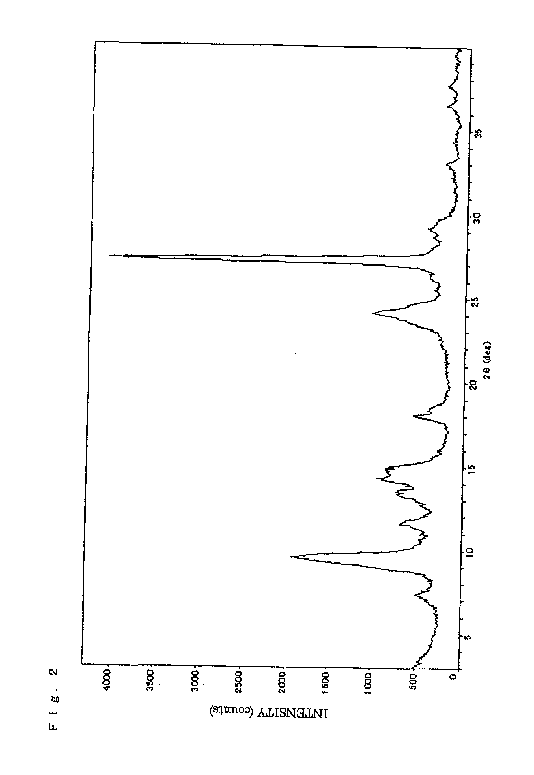
[0082]Especially preferred is oxytitanium phthalocyanine which has a main distinct diffraction peak at a Bragg angle (2θ±0.2°) of 27.2° in an X-ray powder diffraction spectrum obtained with CuKα characteristic X rays.
[0083]It is preferred that the oxytitanium phthalocyanine should have a distinct diffraction peak at a Bragg angle (2θ±0.2°) of 9.0°-9.7° in an X-ray powder diffraction spectrum obtained with CuKα characteristic X rays.

Problems solved by technology

As a result, a possibility of noise generation becomes higher and there is a possibility that toner particles might pass through during slipping to cause a cleaning failure, resulting in a streaky image defect.
There is also a higher possibility that the so-called a filming phenomenon might occur, in which a component of the toner sticks to the photoreceptor surface by the action of the blade pressure and becomes difficult to remove, so as to lead to persistent image defects.
Furthermore, since the photoreceptor is rotated with toners in the state of being strongly pressed thereagainst, the image defects are apt to be caused due to peripheral-direction scratches.
As a result, they have found that by incorporating a specific charge-transporting material and a specific binder resin into the outermost layer of a photoreceptor, the occurrence of troubles such as noise generation, cleaning failures, and occurrence of filming can be inhibited without impairing the other photoreceptor performance.

Method used


Image

  • Electrophotographic photoreceptor, image-forming apparatus, and electrophotographic cartridge
  • Electrophotographic photoreceptor, image-forming apparatus, and electrophotographic cartridge
  • Electrophotographic photoreceptor, image-forming apparatus, and electrophotographic cartridge

Examples


example 1

Production of Coating Fluids

[0187]A coating fluid for undercoat layer formation was produced in the following manner. Rutile titanium oxide having an average primary-particle diameter of 40 nm (“TTO55N”, manufactured by Ishihara Sangyo Kaisha, Ltd.) was mixed with methyldimethoxysilane (“TSL8117”, manufactured by Toshiba Silicone Co., Ltd.), the amount of which was 3% by weight based on the titanium oxide, by means of a Henschel mixer. The resultant surface-treated titanium oxide was dispersed in a mixed solvent composed of methanol and 1-propanol in a weight ratio of 7 / 3 by means of a ball mill to obtain a dispersion slurry of the surface-treated titanium oxide. The dispersion slurry was mixed with a methanol / 1-propanol / toluene mixed solvent and pellets of a copolyamide composed of ε-caprolactam [compound represented by the following formula (A)], bis(4-amino-3-methylcyclohexyl)methane [compound represented by the following formula (B)], hexamethylenediamine [compound represented b...

example 2

[0200]A photoreceptor was produced and evaluated in the same manners as in Example 1, except that a binder resin in which m:n was 80:20 and which had a weight-average molecular weight (Mw) of 50,000 and a number-average molecular weight (Mn) of 20,000 was used. The results obtained are shown in Table 1.

example 3

[0201]A photoreceptor was produced and evaluated in the same manners as in Example 1, except that the compound represented by (1)-11 shown above was used as a charge-transporting material in place of the compound represented by (1)-2 shown above. The results obtained are shown in Table 1.


PUM

PropertyMeasurementUnit
Tgaaaaaaaaaa
Tgaaaaaaaaaa
Tgaaaaaaaaaa

Abstract

When an abutting pressure of the cleaning blade on a photoreceptor is increased, a chattering occurs due to the so-called a stick-slip phenomenon that the blade repeatedly undergoes sticking to the outermost surface of the photoreceptor and slipping thereon. As a result, a possibility of noise generation becomes higher and there is a possibility that toner particles might pass through during slipping to cause a cleaning failure, resulting in a streaky image defect. There is also a higher possibility that the so-called a filming phenomenon might occur, in which a component of the toner sticks to the photoreceptor surface by the action of the blade pressure and becomes difficult to remove, so as to lead to persistent image defects. Furthermore, since the photoreceptor is rotated with toners in the state of being strongly pressed thereagainst, the image defects are apt to be caused due to peripheral-direction scratches. An electrophotographic photoreceptor is provided in which the outermost layer of the photoreceptor contains a specific charge-transporting material and a specific binder resin.

Description

FIELD OF THE INVENTION[0001]The present invention relates to an electrophotographic photoreceptor for use in copiers, printers, or the like, and to an image-forming apparatus and a cartridge. More particularly, the invention relates to an electrophotographic photoreceptor, an image-forming apparatus, and a cartridge which are capable of inhibiting the occurrence of troubles such as noise generation, cleaning failures, and occurrence of filming even when a heavy load is imposed on the electrophotographic photoreceptor as in the case where a spherical toner is used and the cleaning blade is abutted on the photoreceptor at an increased pressure.BACKGROUND OF THE INVENTION[0002]Electrophotography is in extensive use in copiers, printers, and printing machines because of advantages thereof such as, for example, that high-quality images are instantaneously obtained therewith.[0003]With respect to electrophotographic photoreceptors (hereinafter suitably referred to as “photoreceptors”), wh...

Claims


Application Information

Patent Timeline
Patent Type & Authority Applications(United States)
IPC IPC(8): G03G15/00
CPCG03G15/75G03G5/14756G03G5/14708
Inventor FUJII, AKITERU
Owner MITSUBISHI CHEM CORP
Why Eureka
Try Eureka