Method for controlling a flow rate of a pump and method for forming a coated film

a technology of a pump and a flow rate, which is applied in the direction of superimposed coating process, liquid/solution decomposition chemical coating, positive displacement liquid engine, etc., can solve the problem of inefficiency of coating area, inability to make efficient use of the surface area on which the coating is applied, and the difference between the detected signal and the target value. to achieve the effect of stabilizing the flow ra

Inactive Publication Date: 2014-07-03
TATSUMO KK
View PDF3 Cites 2 Cited by
  • Summary
  • Abstract
  • Description
  • Claims
  • Application Information

AI Technical Summary

Benefits of technology

[0018]The present invention makes it possible to stab...

Problems solved by technology

This results in a difference between the detected signal and the target value.
However, a drawback as well as manner of the control peculiar to the feedback mechanism as it is, the signal gains acceleration for the attainment of a quick recovery from shortage; so that after the detected signal reaches a target value at a time TA (T1
Particularly, in applications where the flow rate of the pump 10 has a dire...

Method used


Image

  • Method for controlling a flow rate of a pump and method for forming a coated film
  • Method for controlling a flow rate of a pump and method for forming a coated film
  • Method for controlling a flow rate of a pump and method for forming a coated film

Examples


Embodiment Construction

[0025]A method for controlling a flow rate of a pump according to an embodiment of the present invention is explained below, referring to the drawings. In the following description, a case of using a diaphragm pump having a configuration similar to the one in FIG. 3 is explained, as an example of a positive displacement pump. However, a pump to which the present invention is applied is not limited to a diaphragm pump. For example, it is also applicable to pumps such as piston pump and so forth in which the stick-slip phenomenon can occur.

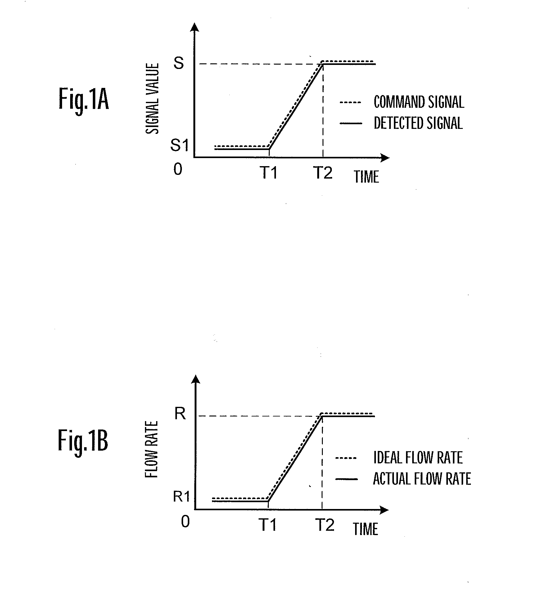
[0026]According to the present invention, as shown in FIG. 1A, a detected signal is made to agree with a command signal by giving a command signal of a minute predetermined signal value S1 beforehand before a time T1 is reached for which a linear motor 12 is kept on standby. That is to say, being brought into a warm-up drive by the minute input, the linear motor 12 is kept beforehand in a state where the stick-slip phenomenon does not occur, i.e. a ...


PUM

PropertyMeasurementUnit
Flow rateaaaaaaaaaa
Frictionaaaaaaaaaa

Abstract

A method for controlling a flow rate of a pump (10) transporting a liquid being driven by a drive system having a sliding portion, wherein a flow rate is maintained at a minute first flow rate (R1) at an early stage of operation of the pump (10); and subsequently the flow rate is increased to a steady second flow rate (R). With the method, at the early stage of operation of the pump (10), a state is established beforehand in which the pump (10) is kept stable at the minute first flow rate in order for the stick-slip phenomenon not to occur; and because the flow rate of the pump is increased from the state, transition from static friction to kinetic friction does not occur; and thus a disorderly flow rate of the pump (10) due to the stick-slip phenomenon of a motor (12) is suppressed.
This makes it possible to attain a stable control of the flow rate at the early stage of operation of the pump (10).

Description

TECHNICAL FIELD[0001]The present invention relates to a method for controlling a flow rate of a pump transporting a liquid, and to a method for forming a coated film by discharging a coating compound transported by the pump onto a surface to be coated.BACKGROUND ART[0002]Generally speaking, in positive displacement pumps such as piston pump, diaphragm pump and so forth used for liquid transportation, a minute stick-slip phenomenon occurs because of a sliding portion the pumps each have; so that a flow rate of such a pump is controlled by a motor such as a servomotor provided with a feedback mechanism in order to recover a time and / or a positional delay (for example, refer to Patent Literature 1).[0003]FIG. 3 is a block diagram showing a general configuration of an example of such a diaphragm pump. The pump 10 comprises a main body 11, a linear motor 12, a piston 13, a diaphragm 14, a connecting block 16, a linear motor block 17 and a linear motor guide 18.[0004]In one end face of th...

Claims


Application Information

Patent Timeline
IPC IPC(8): F04B49/02B05D1/40
CPCB05D1/40F04B49/02F04B49/106B05C5/02B05C11/1002B05D1/26F04B13/00G05D7/06
Inventor IKAGAWA, YOSHINORI
Owner TATSUMO KK
Why Eureka
Try Eureka