Guidance device for moving chain

A guiding device and chain-feeding technology, which is applied to conveyors, transportation and packaging, and can solve problems such as deterioration of the conveying environment, changes in the speed of roller chains, and defective products

Inactive Publication Date: 2004-09-01
TSUBAKIMOTO CHAIN CO
View PDF0 Cites 4 Cited by
  • Summary
  • Abstract
  • Description
  • Claims
  • Application Information

AI Technical Summary

Problems solved by technology

[0005] But the pulsation preventing device of existing sprocket drive chain is designed so that the center of the roller pivotally connected on the roller chain enters the drive sprocket along the tangent of the meshing pitch circle. Polygonal motion at the meshing position with the drive sprocket causing a change in the speed of the roller chain
[0006] In addition, due to the speed change of the roller chain, there are the following problems: the so-called tenon and groove phenomenon that causes inversion and roll-off on the conveyed goods on the conveyor belt; the so-called seasickness caused by the back and forth movement of the assembled goods on the assembly line Phenomena lead to defective products; roller chain tension changes require excessive driving power to increase the size of the chain; increased vibration and noise worsen the handling environment, etc.

Method used


Image

  • Guidance device for moving chain
  • Guidance device for moving chain
  • Guidance device for moving chain

Examples


Embodiment Construction

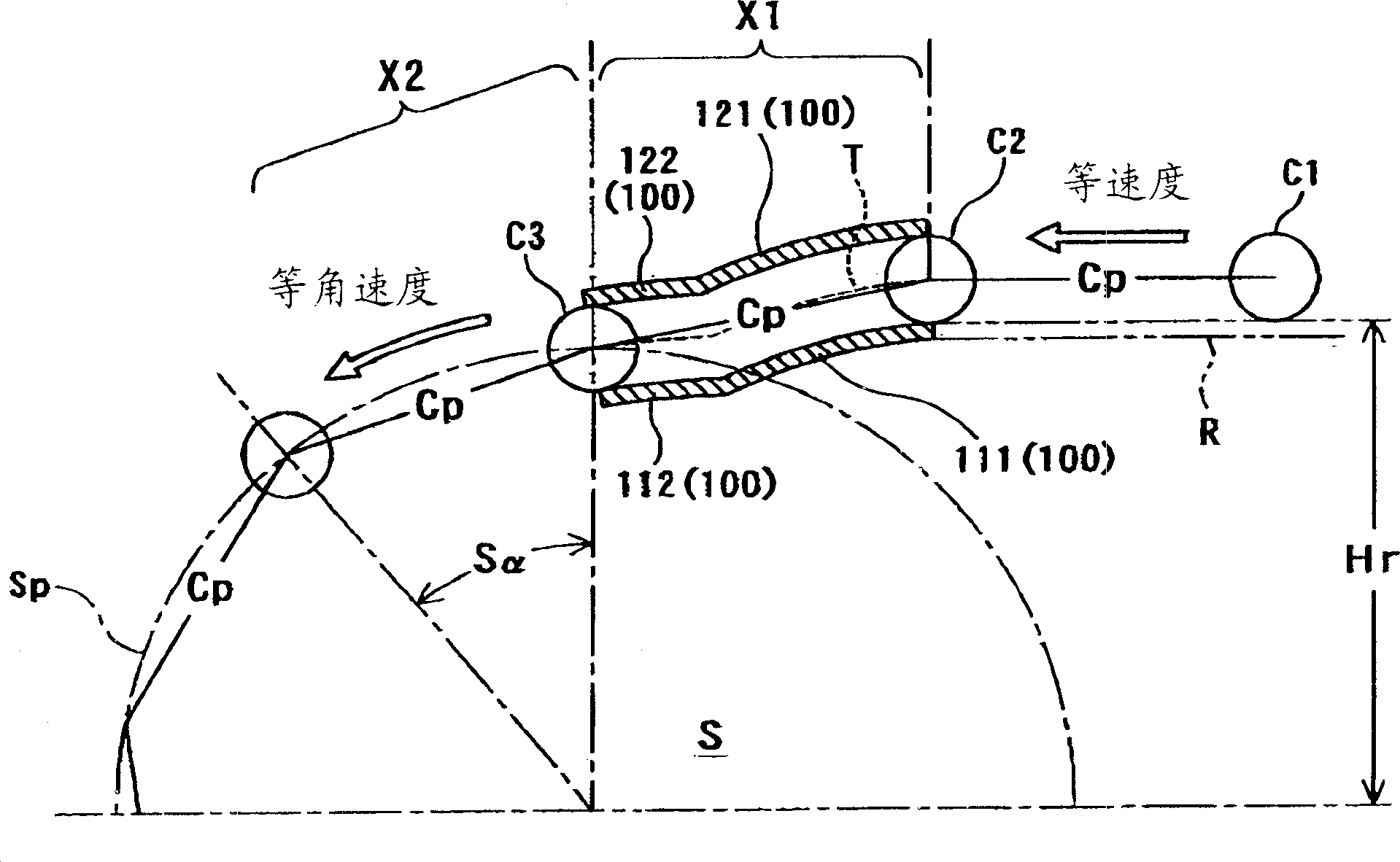
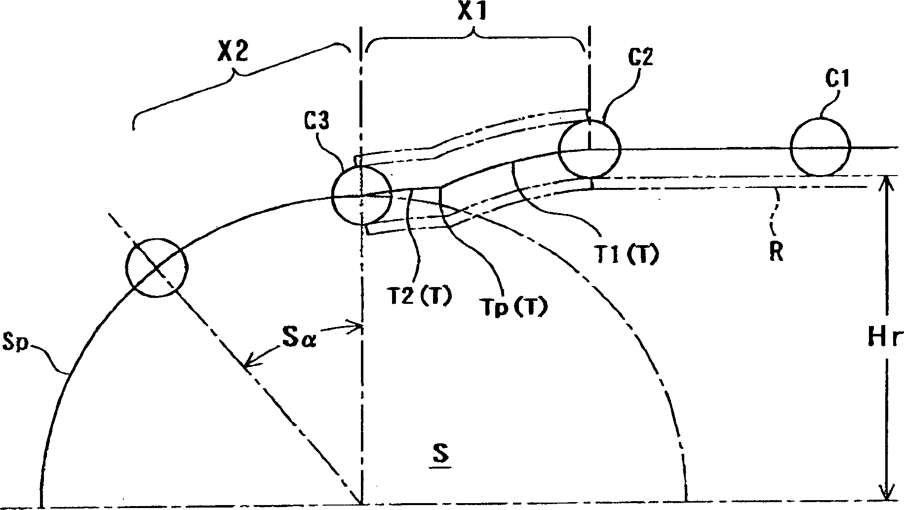
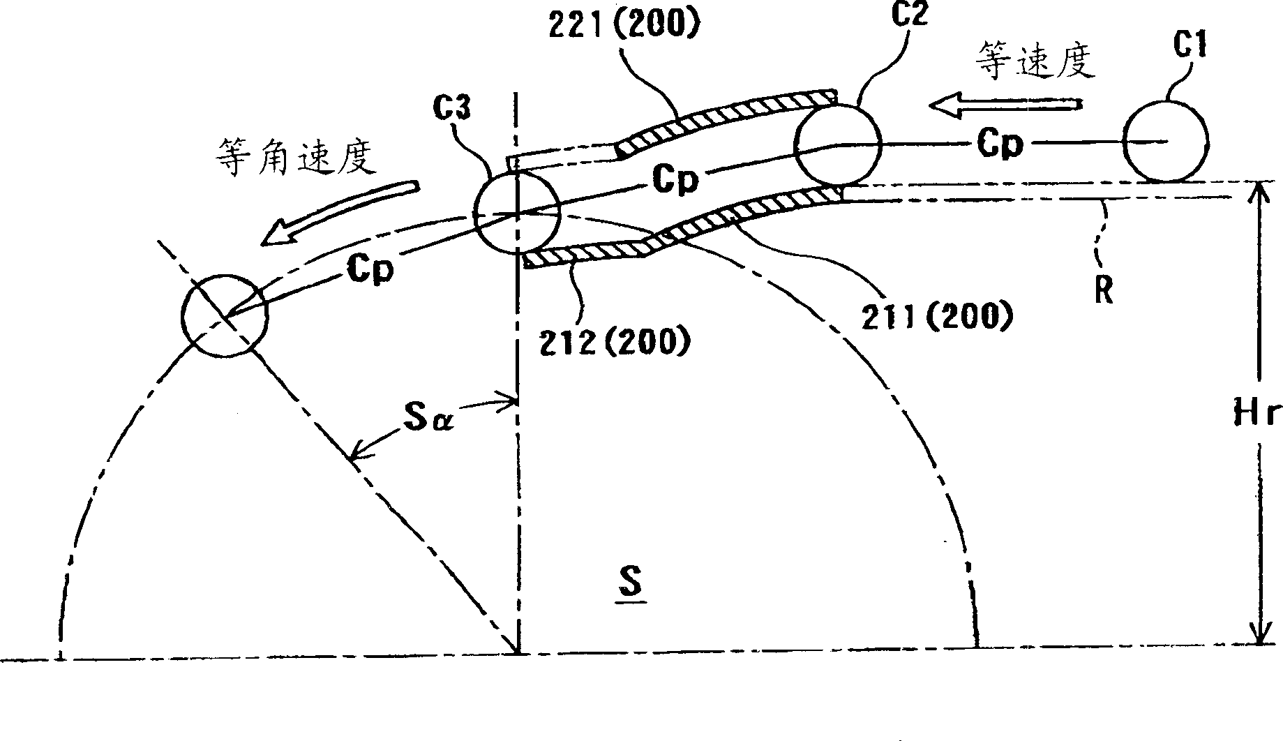
[0039] Embodiments of the preferred embodiments of the guide device for conveying chains according to the present invention will be described below with reference to the accompanying drawings. here, figure 1 It is an installation diagram of the conveyance chain guide device 100 of the first embodiment of the present invention, figure 2 is a diagram showing the moving path of the rollers of the conveyor chain, image 3 It is an installation diagram of the guide device 200 for the conveyance chain of the second embodiment of the present invention, Figure 4 It is an installation diagram of the guide device 300 for the conveyance chain of the third embodiment of the present invention, Figure 5 It is an installation diagram of the guide device 400 for conveying chains of the fourth embodiment of the present invention, Figure 6 It is an installation diagram of the guide device 500 for conveyance chains of the fifth embodiment of the present invention.

[0040] Such as figu...


PUM


Abstract

A conveying chain guide, in which the stick slip phenomenon of a conveying chain, which meshes with a driving sprocket, and a seasickness phenomenon are removed whereby stable conveying of articles can be smoothly realized and the driving force and vibration noise of a conveying chain can be remarkably reduced. When continuous three rollers C1, C2, C3 in the conveying chain C is to be meshed with the sprocket while gradually descending from the linear rail R for supporting the conveying surface toward the driving sprocket S, in such an arrangement traveling state that always corresponds to the linear rail R for supporting the conveying surface, a transfer position X1 and a meshing position X2, the guide track T is defined along an movement passage of the roller C2 in the transfer position X1.

Description

technical field [0001] The present invention relates to a guide device for a conveyor chain for eliminating speed variations of a conveyor chain which engages with a driving sprocket and moves polygonally on a conveyor belt for conveying articles. Background technique [0002] In the prior art, there is such a pulsation preventing device for a sprocket drive chain, which is equipped with a deflection guide member having a deflection arc surface, and the deflection arc surface is suspended on the side of the drive sprocket for rotation. abutting against the rollers of the roller chain and biasing the chain to suspend and guide rotation on the aforementioned sprockets, the chain length L between the rollers of the aforementioned roller chain and the respective points of initial contact of the aforementioned deflection guide members and drive sprocket teeth and The relationship between the pitch P of the chain is L=(n+0.5)×P, and the so-called pulsation, which is uneven rotatio...

Claims


Application Information

Patent Timeline
Patent Type & Authority Applications(China)
IPC IPC(8): B65G17/48B65G21/22
CPCB65G17/48B65G21/22
Inventor 铃木健之园田胜敏
Owner TSUBAKIMOTO CHAIN CO
Why Eureka
Try Eureka