Method and apparatus for achieving transparent redundancy at a hierarchical boundary

Inactive Publication Date: 2007-09-11
RPX CLEARINGHOUSE
View PDF7 Cites 135 Cited by
  • Summary
  • Abstract
  • Description
  • Claims
  • Application Information

AI Technical Summary

Benefits of technology

[0019]According to another embodiment, redundancy is provided at a hierarchical boundary between an MPLS domain and an Ethernet domain. Specifically, redundancy is achieved within the Ethernet domain by treating each boundary network device analogously to a router in the VRRP scheme for routers. Boundary network devices are grouped into boundary network device redundancy groups, in which all boundary network devices have knowledge of each other, and one is designated as master and the

Problems solved by technology

This introduces a number of challenges in creating a highly reliable network, as hierarchical boundaries are normally single points of failure in the network, and an arbitrary number of hierarchical boundaries may be traversed by a given end-to-end path across the network.
As data networks have grown in complexity and speed, the network devices used in those networks have likewise increased in complexity and speed.
Unfortunately, this complexity provides manifest opportunities for the network to fail.
As services offered over networks become increasingly complex, for example layer 2 and layer 3 virtual private networks (VPNs) are deployed, and virtual private LAN segment (VPLS) services are made available, redundancy becomes increasingly important, and also increasingly difficult.
MPLS provide

Method used


Image

  • Method and apparatus for achieving transparent redundancy at a hierarchical boundary
  • Method and apparatus for achieving transparent redundancy at a hierarchical boundary
  • Method and apparatus for achieving transparent redundancy at a hierarchical boundary

Examples


Embodiment Construction

[0026]The following detailed description sets forth numerous specific details to provide a thorough understanding of the invention. However, those skilled in the art will appreciate that the invention may be practiced without these specific details. In other instances, well-known methods, procedures, components, protocols, algorithms, and circuits have not been described in detail so as not to obscure the invention.

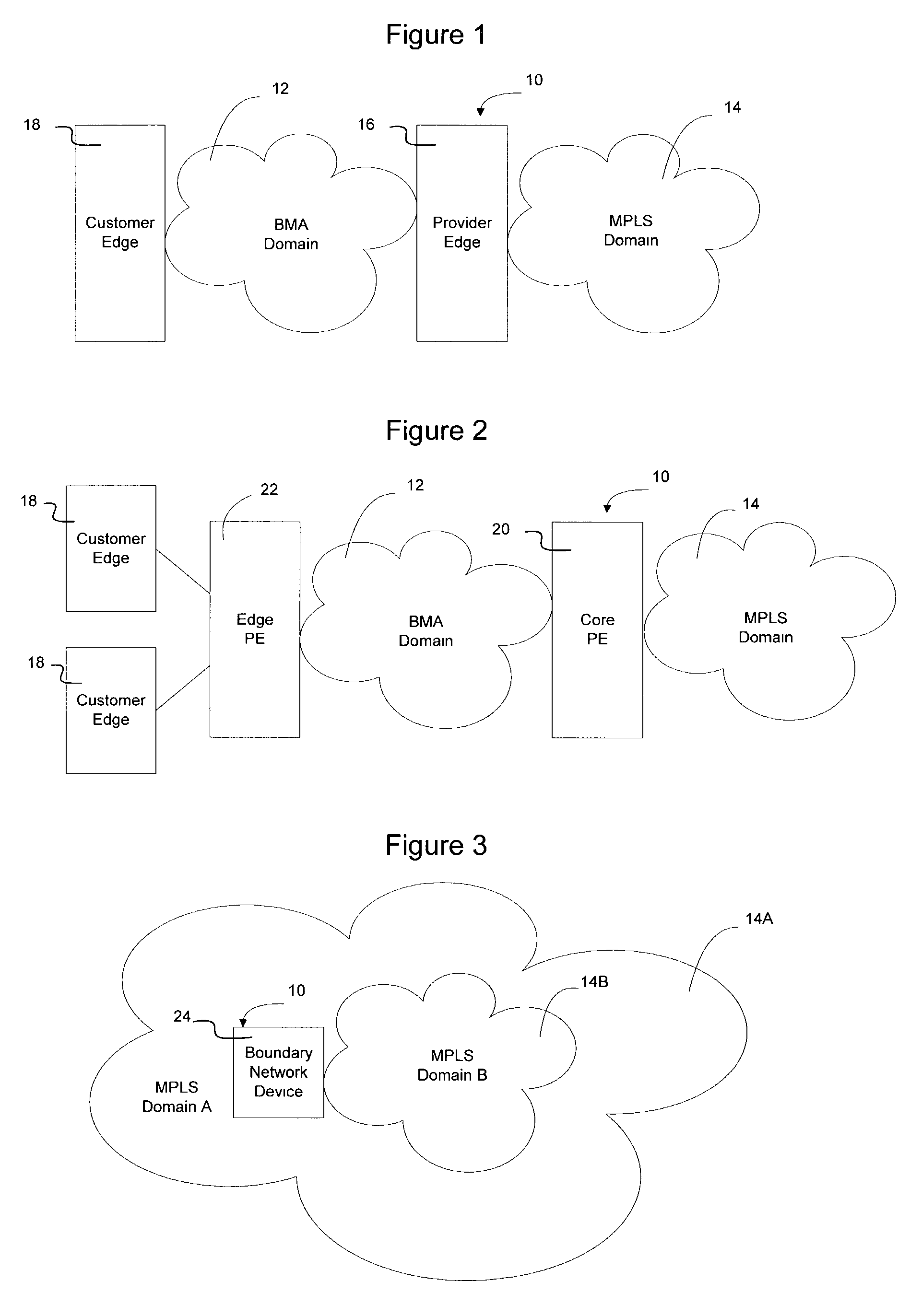
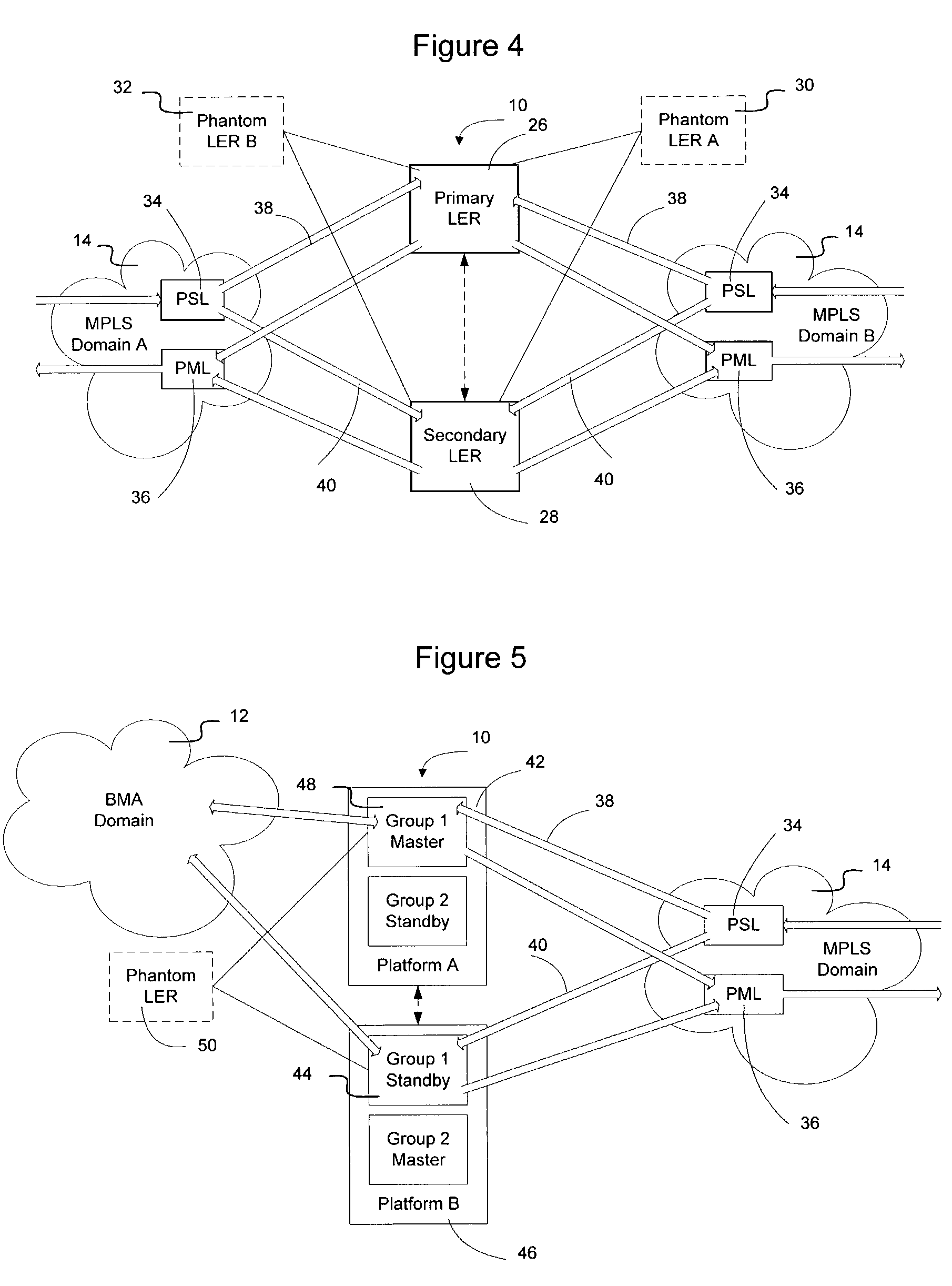
[0027]As described in greater detail below, the method and apparatus of the present invention provides improved resiliency of the network by providing transparent redundancy at a hierarchical boundary. Specifically, redundancy may be provided at a MPLS-MPLS hierarchical boundary or at a BMA-MPLS hierarchical boundary by utilizing local repair mechanisms extant in the domains to select automatically, in each domain, the same boundary network devices as the primary and secondary boundary network devices. Thus, transparent redundancy may be established at the hierarchical bo...


PUM


Abstract

Transparent redundancy may be achieved at a MPLS-MPLS hierarchical boundary or a BMA-MPLS hierarchical boundary by utilizing local repair mechanisms extant in each domain to select automatically the same boundary network devices as the primary and secondary boundary network devices. In the MPLS domain, two LERs advertise the ability to forward traffic to a phantom LER and map all traffic originated into that domain as having been on a path originating at the phantom LER. This will cause the LERs to appear as being one hop away from the phantom LER, causing MPLS to assume the real LERs are part of a LSP terminating at the phantom LER. MPLS local repair will thus establish one of the LERs as the primary LER and the other LER as the secondary LER. In an Ethernet domain, each boundary network device is treated analogously to a router in the VRRP scheme for routers.

Description

BACKGROUND OF THE INVENTION[0001]1. Field of the Invention[0002]The present invention relates to communication networks and, more particularly, to a method and apparatus for achieving transparent redundancy at a hierarchical boundary in a communication network.[0003]2. Description of the Related Art[0004]Data communication networks may include various computers, servers, nodes, routers, switches, hubs, proxies, and other devices coupled to and configured to pass data to one another. These devices will be referred to herein as “network devices.” Data is communicated through the data communication network by passing data packets (or data cells or segments) between the network devices by utilizing one or more communication links. A particular packet may be handled by multiple network devices and cross multiple communication links as it travels between its source and its destination over the network.[0005]The various network devices on the communications network communicate with each ot...

Claims


Application Information

Patent Timeline
IPC IPC(8): G01R31/00H04J3/14H04L12/26H04L12/56
CPCH04L41/0663
Inventor CASEY, LIAM MAURICEALLAN, DAVID IAN
Owner RPX CLEARINGHOUSE
Why Eureka
Try Eureka