Power supply system supporting redundancy backup and hot plugging

A redundant backup and power supply system technology, which is applied in the field of redundant power supply, can solve problems such as prone to sparking, complex system implementation, and no current sharing function.

Active Publication Date: 2015-01-28
BANGYAN TECH
View PDF3 Cites 12 Cited by
  • Summary
  • Abstract
  • Description
  • Claims
  • Application Information

AI Technical Summary

Problems solved by technology

[0003] At present, in the MT (MicroTCA: Micro Telecommunications Computing Architecture) platform or AT (ATCA: Advanced Telecommunications Computing Platform) platform, products in the military market all use dual power supply systems to achieve redundant backup, thereby achieving improved The purpose of product reliability, however, the current common method is to use the current method to achieve, figure 1 It is a schematic structural diagram of a dual power supply system in the prior art, such as figure 1 As shown, there are multiple service boards connected to the backplane, and the backplane is powered by two power supply systems of power supply 1 and power supply 2 to realize redundant backup. The main defect of this method is that each power supply system must have a However, there are quite a few power supply systems on the market at present without the current sharing function; without this function, redundant backup cannot be realized; also, the result of the current sharing function is that both modules are running The work of the load, such a result can only realize the redundant function, but cannot realize the backup function; also, if this kind of realization method is implemented, if the hot swap is realized, it is easy to cause sparking phenomenon, because the current MT and AT equipment, work The current is relatively large, and the general DC 48V power supply part can generally reach more than 5A; if you suddenly dial and plug in during work, it is easy to cause ignition.
[0004] Another technique is to add a monitoring system. The disadvantage of this method is that the system is complex to realize. The power supply switching of the dual power supply system is not realized actively by the power supply system itself, but is realized through passive switching of the monitoring system.

Method used


Image

  • Power supply system supporting redundancy backup and hot plugging
  • Power supply system supporting redundancy backup and hot plugging
  • Power supply system supporting redundancy backup and hot plugging

Examples


Embodiment Construction

[0034] The principles and features of the present invention are described below in conjunction with the accompanying drawings, and the examples given are only used to explain the present invention, and are not intended to limit the scope of the present invention.

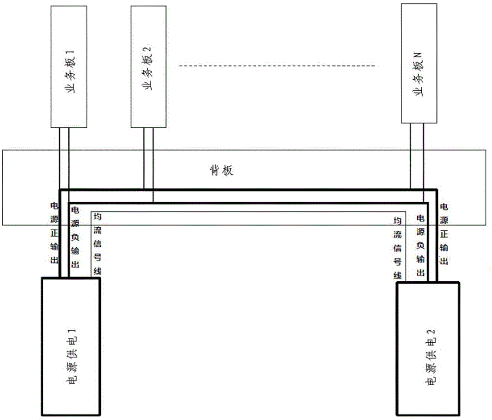
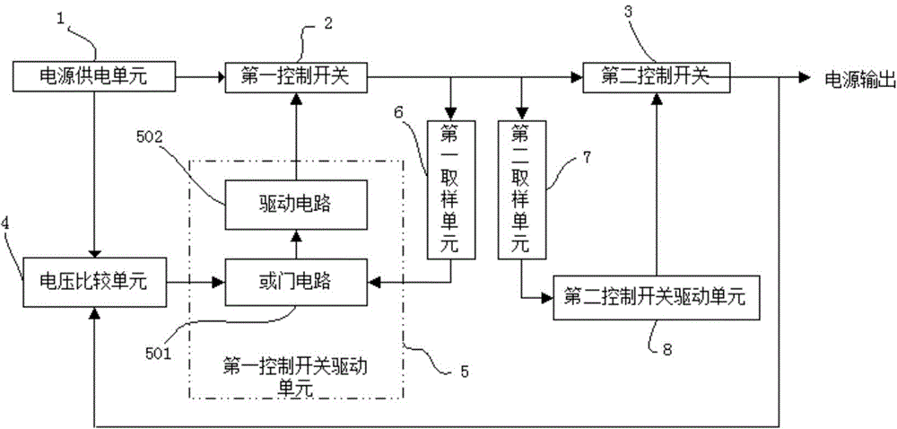
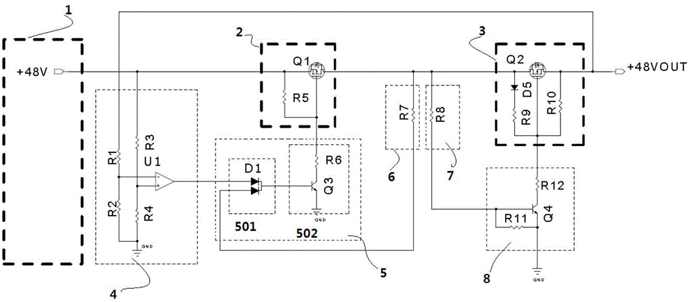
[0035] A power supply system supporting redundant backup and hot swap of the present invention includes at least two power supply systems, figure 2 It is a structural block diagram of a power supply system that supports redundant backup and hot swapping, such as figure 2 As shown, the power supply module includes: a power supply unit 1, a first control switch 2, a second control switch 3, a first controllable switch drive unit 5, a second control switch drive unit 8, a voltage comparison unit 4, a first sampling Unit 6, the second sampling unit 7.

[0036] Wherein, the power supply unit 1 is used to generate the working voltage;

[0037] The first control switch 2 is a main voltage control circuit, which mainly ...


PUM


Abstract

The invention discloses a power supply system supporting redundancy backup and hot plugging, comprising at least two power supply systems. Each power supply system comprises a power supply unit, a first control switch, a second control switch, a first controllable switch driving unit, a second controllable switch driving unit, a voltage comparison unit, a first sampling unit, and a second sampling unit. Under the condition that the power supply system is not current-shared, power supply switching can be carried out automatically, and a redundancy backup function can be achieved; and hot plugging is carried out without spark or power cut, and no other auxiliary connecting line is needed except the connection of two output voltages between the power supply systems. In addition, power supply system switching is actively implemented by the power supply system itself, no external monitoring system is needed, and redundancy and backup functions are truly achieved. The power supply system supporting redundancy backup and hot plugging can be widely applied to the field of redundant power supplies.

Description

technical field [0001] The invention relates to a redundant power supply, in particular to a power supply system supporting redundant backup and hot swapping. [0002] Background technique [0003] At present, in the MT (MicroTCA: Micro Telecommunications Computing Architecture) platform or AT (ATCA: Advanced Telecommunications Computing Platform) platform, products in the military market all use dual power supply systems to achieve redundant backup, thereby achieving improved The purpose of product reliability, however, the current common method is to use the current method to achieve, figure 1 It is a schematic structural diagram of a dual power supply system in the prior art, such as figure 1 As shown, there are multiple service boards connected to the backplane, and the backplane is powered by two power supply systems of power supply 1 and power supply 2 to realize redundant backup. The main defect of this method is that each power supply system must have a However, t...

Claims


Application Information

Patent Timeline
Patent Type & Authority Applications(China)
IPC IPC(8): H02J9/06
CPCH02J9/06
Inventor 吴新祥
Owner BANGYAN TECH
Why Eureka
Try Eureka