
Blower filter device, respiratory protection device, operational infrastructure and method

a filter device and filter technology, applied in the direction of machines/engines, liquid fuel engines, wireless commuication services, etc., can solve the problems of difficult mutual assistance, inability of users, etc., to avoid drawbacks of the state of the art, facilitate assistance by other team members, and improve the perceptibility of alarms

Inactive Publication Date: 2017-01-05
DRAGER SAFETY
View PDF7 Cites 10 Cited by
  • Summary
  • Abstract
  • Description
  • Claims
  • Application Information

AI Technical Summary

Benefits of technology

The present invention provides a blower filter device, a respirator system, and an operational infrastructure with improved alarm notification and recognition for better decision-making. The output unit of the device can distinguish between primary and secondary alarms based on their origin and type, which can be useful in identifying the member of the team involved. The communication interface also acts as a gateway to transmit messages to other participants, ensuring redundancy in message transmission even under difficult conditions.

Problems solved by technology

Depending on the operating conditions, the user is, however, often unable due to the environmental situation to perceive visual signals if carrying the apparatus on the user's back or even acoustic signals in situations associated with a high noise level.
It is also possible under adverse conditions that an alarm originating from a blower filter device is not perceived by the persons located in the vicinity in missions in which a plurality of persons work in a team; a mutual assistance is often difficult in such situations.

Method used


Image

  • Blower filter device, respiratory protection device, operational infrastructure and method
  • Blower filter device, respiratory protection device, operational infrastructure and method
  • Blower filter device, respiratory protection device, operational infrastructure and method

Examples


Embodiment Construction

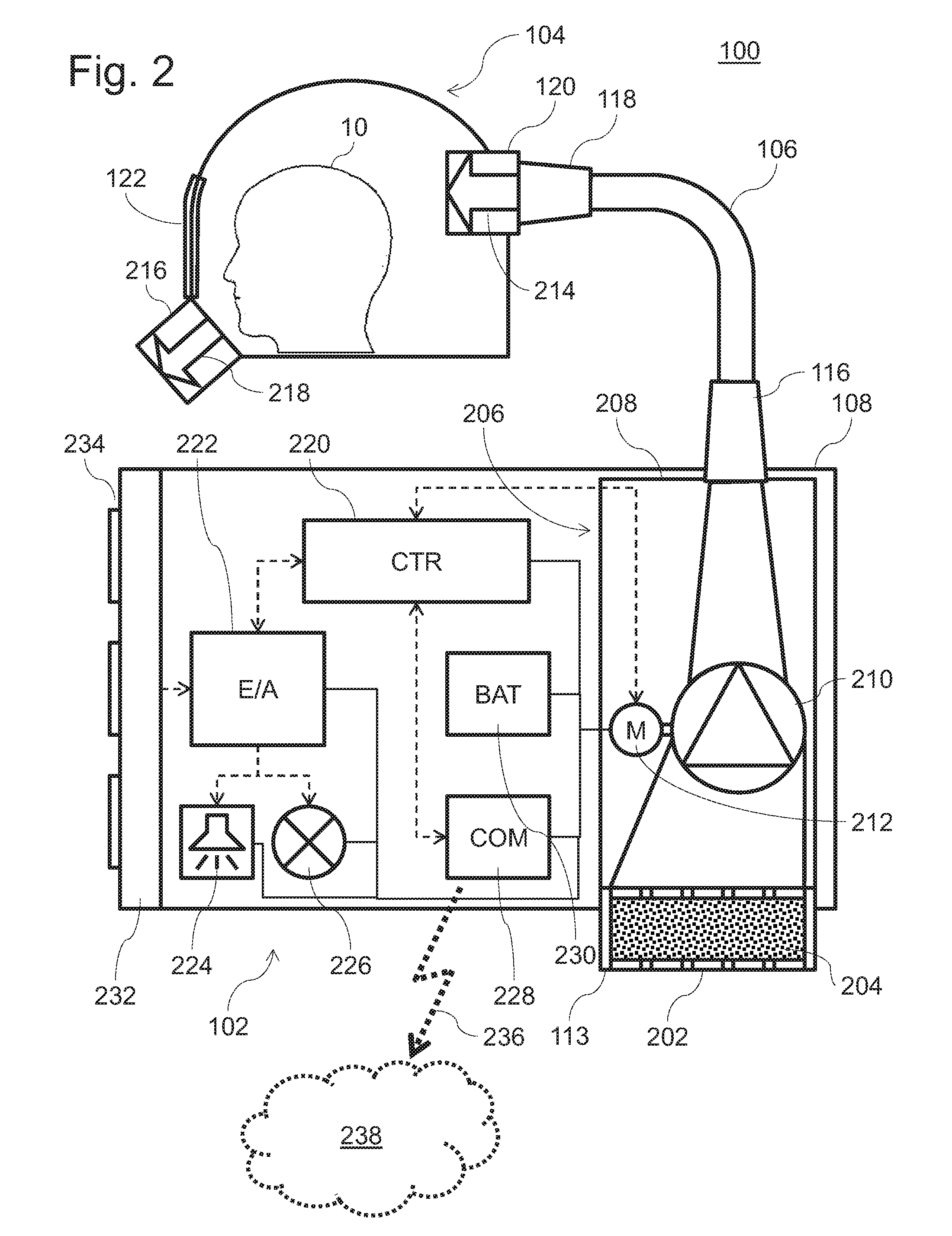
[0033]Exemplary embodiments of the present invention will be described below in detail on the basis of the attached drawings. Identical components shown in different figures are always designated by the same reference numbers. Components and features, purposes and effects, which are described in reference to an exemplary embodiment, are to be assumed to be applicable in all other exemplary embodiments, unless this is expressly or obviously ruled out, and they shall also be considered to be disclosed in reference to the respective other exemplary embodiment, even if they are not expressly shown and / or described there. It is obvious, furthermore, that the drawings shall be considered to be schematic drawings and no restrictions in respect to concrete dimensions or size ratios shall be attributed to them, unless such restrictions are expressly described.

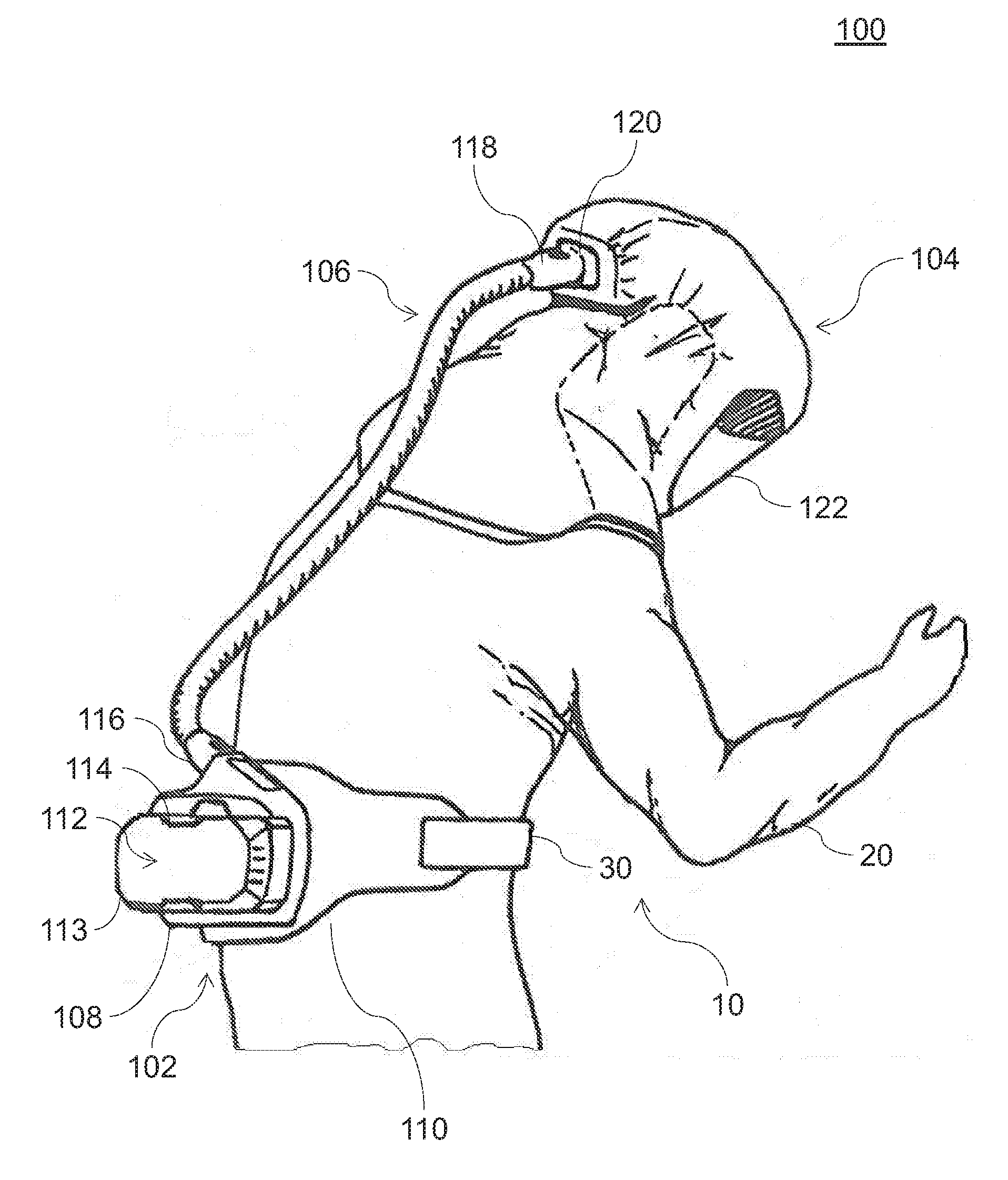
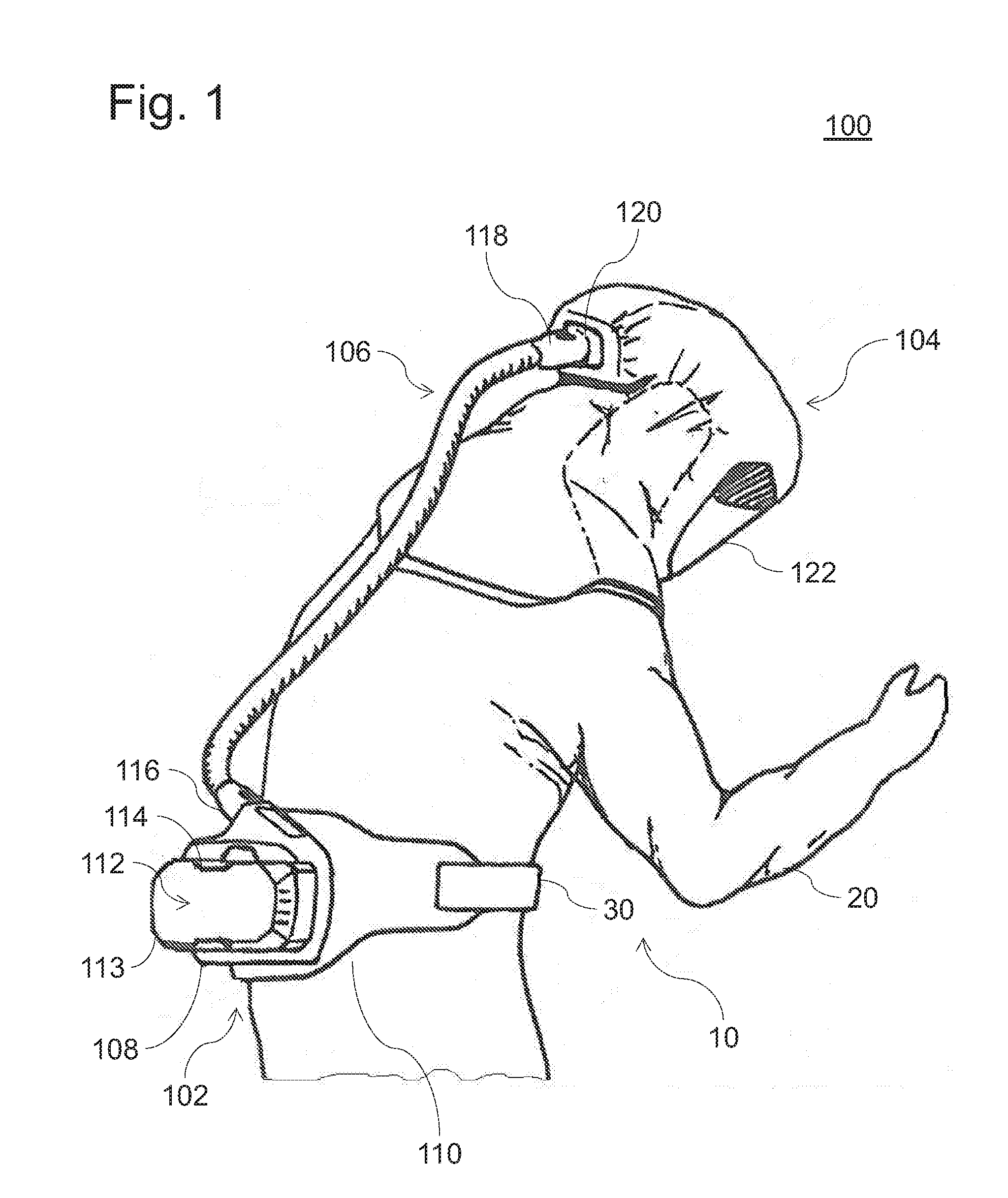
[0034]FIG. 1 schematically shows a respirator system 100 as an exemplary embodiment of the present invention. The respirator system 10...


PUM


Abstract

A blower filter device includes a blower unit that draws and delivers ambient air; a filter unit that filters a harmful substance, or a filter coupling to couple and uncouple the filter unit. A control unit is configured to actuate the blower unit, to determine an operating state of the blower filter device and / or other respirator system components and / or a respirator system (100) as a whole and to generate an alarm if a determined operating state indicates a disturbance. An output unit is configured to receive the alarm from the control unit and to output the alarm. A communication interface (228) is configured for wireless network integration and to transmit the alarm via the network (238). A respirator system (100) with such a blower filter device, an operational infrastructure (300) with such a respirator system, as well as a method of blower filter operation and operational infrastructure monitoring are provided.

Description

CROSS REFERENCE TO RELATED APPLICATIONS[0001]This application is a United States National Phase Application of International Application PCT / EP2014 / 003125 filed Nov. 24, 2014 and claims the benefit of priority under 35 U.S.C. §119 of German Patent Application 10 2013 018 053.8 filed Nov. 28, 2013 the entire contents of which are incorporated herein by reference.FIELD OF THE INVENTION[0002]The present invention pertains to a blower filter device, a respirator system respiratory protection device, an operational (use) infrastructure as well as methods for operating a blower filter device and for monitoring an operational infrastructure.BACKGROUND OF THE INVENTION[0003]Respirator systems with blower filter devices are used for light and medium respiration protection and they support the user of respirator filters by reducing the respiration resistance, unlike conventional gas masks, and make possible a long, fatigue-free use of the respirator as a result.[0004]A conventional respirator...

Claims


Application Information

Patent Timeline
IPC IPC(8): A62B9/00F04D29/42F04D29/28F04D25/08F04D25/06H04W4/00A62B9/04A62B18/00A62B18/04A62B17/04A62B18/02F04D29/70A62B23/02H04W4/80
CPCA62B9/006F04D29/703F04D29/4206F04D29/281F04D25/08F04D25/0673H04W4/008A62B9/04A62B18/006A62B18/045A62B17/04A62B18/02A62B23/02H04W4/80
Inventor VOLMER, ACHIMDEHMKE, MATHIASPERNOT, THOMASROMBA, MARCUS
Owner DRAGER SAFETY
Learn More