Laser line generating device with swivel base

a technology of generating device and swivel base, which is applied in the direction of mechanical measuring arrangement, machine supports, instruments, etc., can solve the problems of limited brightness, inconvenient for certain uses, and permanent problem of surface alignmen

Inactive Publication Date: 2007-09-18
IRWIN IND TOOL CO
View PDF180 Cites 36 Cited by
  • Summary
  • Abstract
  • Description
  • Claims
  • Application Information

AI Technical Summary

Problems solved by technology

Alignment of surfaces is a perennial problem in a variety of fields, ranging from construction to interior decorating.
However, some of these products are cumbersome, and others are not suitable for certain uses.
A visible, straight laser line is acceptable, but may be limited in its brightness over a distance, and may also tend to defocus and become dimmer as a user works further away from the source of the laser.
As a result, such devices may have limited utility or may not work in confined spaces requiring a longer alignment tool.
Moreover, a conventional laser is not well-equipped for projecting a flat or planar beam of light.
Another aspect of laser alignment products that could be improved is the inability of laser devices to work around obstructions.
That is, if a wall-hanging, such as a picture frame, interrupts the laser beam, it may be blocked from further projection.
Obstructions may include moldings placed in a doorway, picture frames in the way of those being aligned on one horizontal line, the operator of the device, other obstacles, or even textured or stuccoed surfaces on interior walls.
Another aspect of laser alignment products that could be improved is the inability of laser alignment devices to rotate or pivot relative the wall or object on which the laser light is intended to operate.
With such limitations, a user must mark a first laser line, move the laser alignment devices angularly relative to the first mark, and then project and mark a second laser line.
As a result of having to move laser alignment device and mark the laser line several times, inaccuracies in the measurements may occur, the wall may more easily become damaged, and unnecessary time is wasted.
A conventional laser beam projector is thus not able to project a laser line on the wall on which it is mounted, nor can it go around obstructions.
The ability to work around obstacles would save much time and effort.
While leveling is necessary, such sophistication as a tripod adds to the expense and bulkiness of the leveling device.

Method used


Image

  • Laser line generating device with swivel base
  • Laser line generating device with swivel base
  • Laser line generating device with swivel base

Examples


Embodiment Construction

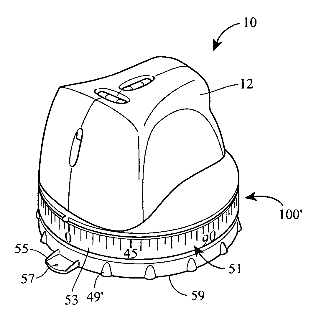
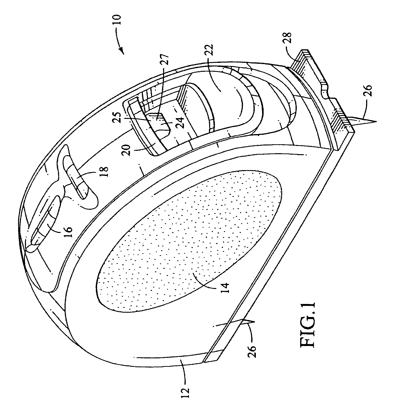
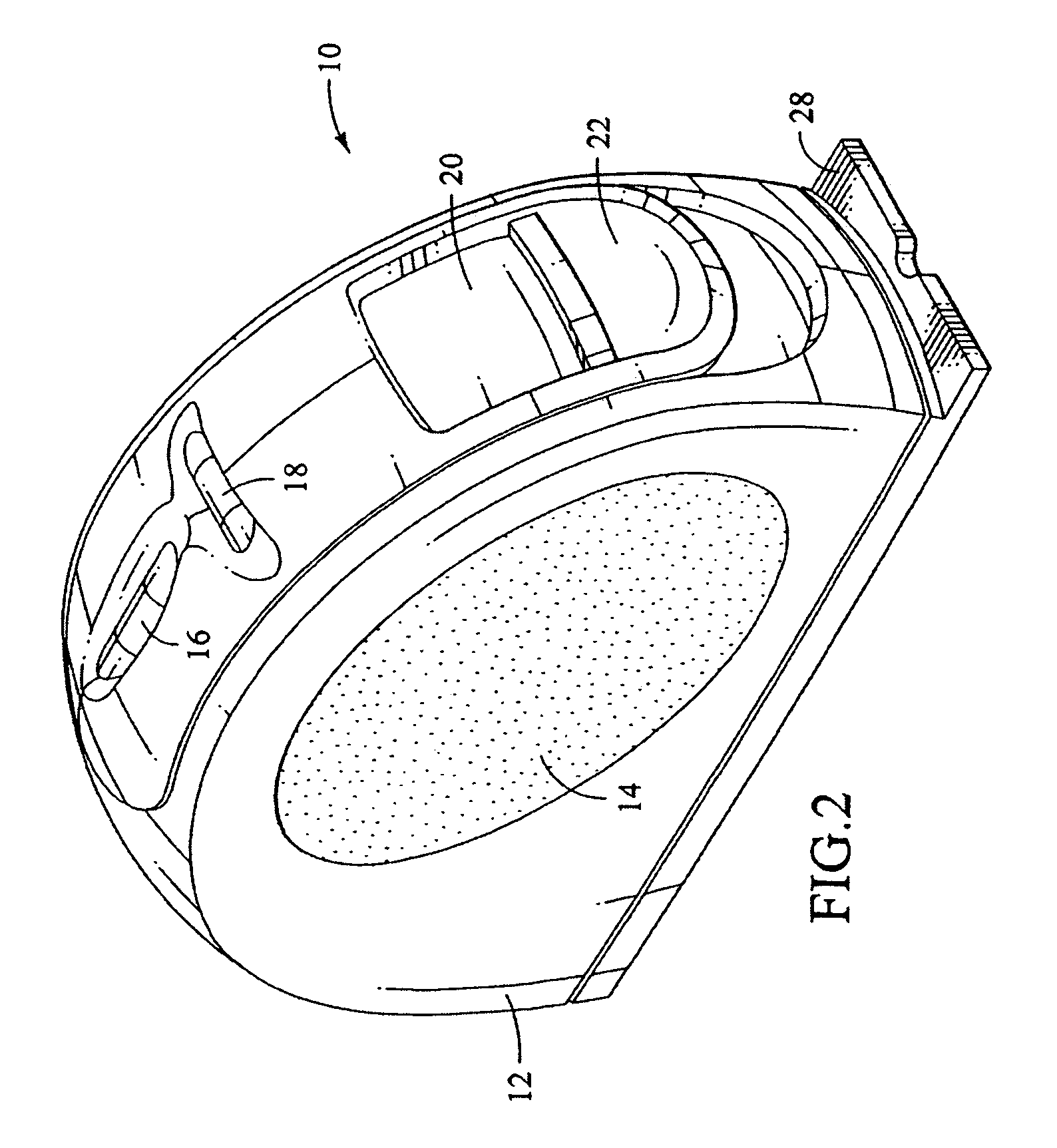
[0030]The present invention is better understood by reference to the figures and description below. FIG. 1 presents a view of a leveling device, such as laser alignment device and generator 10. The generator 10 comes in a housing 12, which may be made of plastic or other suitable material such as metal, and it possesses a handgrip area 14 for handling, the area 14 preferably made of an elastomeric substance for easier gripping. The generator 10 may have a first leveling indicator 16 such as a spirit level or “bubble” level for orientating or leveling the generator 10 in a first plane. If desired, the level indicator may be selected from the group consisting of a pendulum, a cantilevered tilt mechanism, an electronic leveler, and a shaft held between journals or leveling in one plane, such as horizontal or vertical. The generator 10 may also have a second leveling indicator 18, for orientation or leveling in a second plane perpendicular to the first plane. The housing 12 may also con...


PUM


Abstract

A laser alignment device includes a laser generating device, an upper attachment portion, and a lower attachment portion. The laser generating device includes a housing and a laser generator. The upper attachment portion is disposed near a bottom of the housing, and the lower attachment portion is pivotally and / or rotationally connected to the upper attachment portion.

Description

RELATED APPLICATION DATA[0001]The present application is a continuation-in-part application based on, and claiming the priority benefit of, co-pending U.S. application Ser. No. 10 / 612,035, which was filed on Jul. 1, 2003, and which is expressly incorporated by reference herein.FIELD OF THE INVENTION[0002]The technical field of the disclosure is that of alignment devices and, in particular, an alignment device and an attachment that allows the alignment device to be releasably attached to a surface on which alignment is desired and that is able to rotate and pivot relative to that surface.BACKGROUND[0003]Alignment of surfaces is a perennial problem in a variety of fields, ranging from construction to interior decorating. Alignment is necessary for walls that should be perpendicular to a floor, or otherwise plumb. Masonry and brick-laying practitioners are well aware of the importance of plumbed and aligned surfaces and chalk lines. A home interior decorated with pictures and other wa...

Claims


Application Information

Patent Timeline
Patent Type & Authority Patents(United States)
IPC IPC(8): G01C15/00G02B3/04
CPCG01C15/004G01C15/008G02B3/04Y10S33/21
Inventor LEVINE, STEVEN R.SPANSKI, JEFFREY L.SMITH, JOHN C.NASH, DEREK J.GIST, LESLIE DAILY
Owner IRWIN IND TOOL CO
Why Eureka
Try Eureka