
Secure electronic voting device

a voting device and electronic technology, applied in the field of voting devices, can solve the problems of tampering schemes, high-tech electronic voting machines, tedious process of collecting, counting and tabling paper ballots, etc., and achieve the effect of preventing alteration and/or reading

Inactive Publication Date: 2007-09-18
GOOGLE LLC
View PDF9 Cites 11 Cited by
  • Summary
  • Abstract
  • Description
  • Claims
  • Application Information

AI Technical Summary

Benefits of technology

[0020]It is a further aspect of the present invention to provide a secure electronic voting device with an inherently reliable and unalterable electronic audit trail.
[0021]It is a further aspect of the present invention to provide a secure electronic voting device that maintains ballot secrecy.
[0022]It is a further aspect of the present invention to provide a secure electronic voting device that prevents alteration and / or reading by unauthorized individuals.
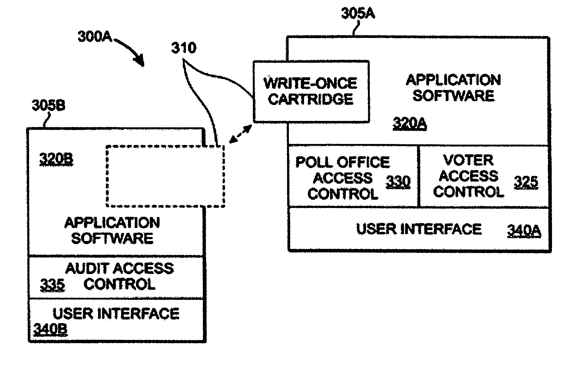
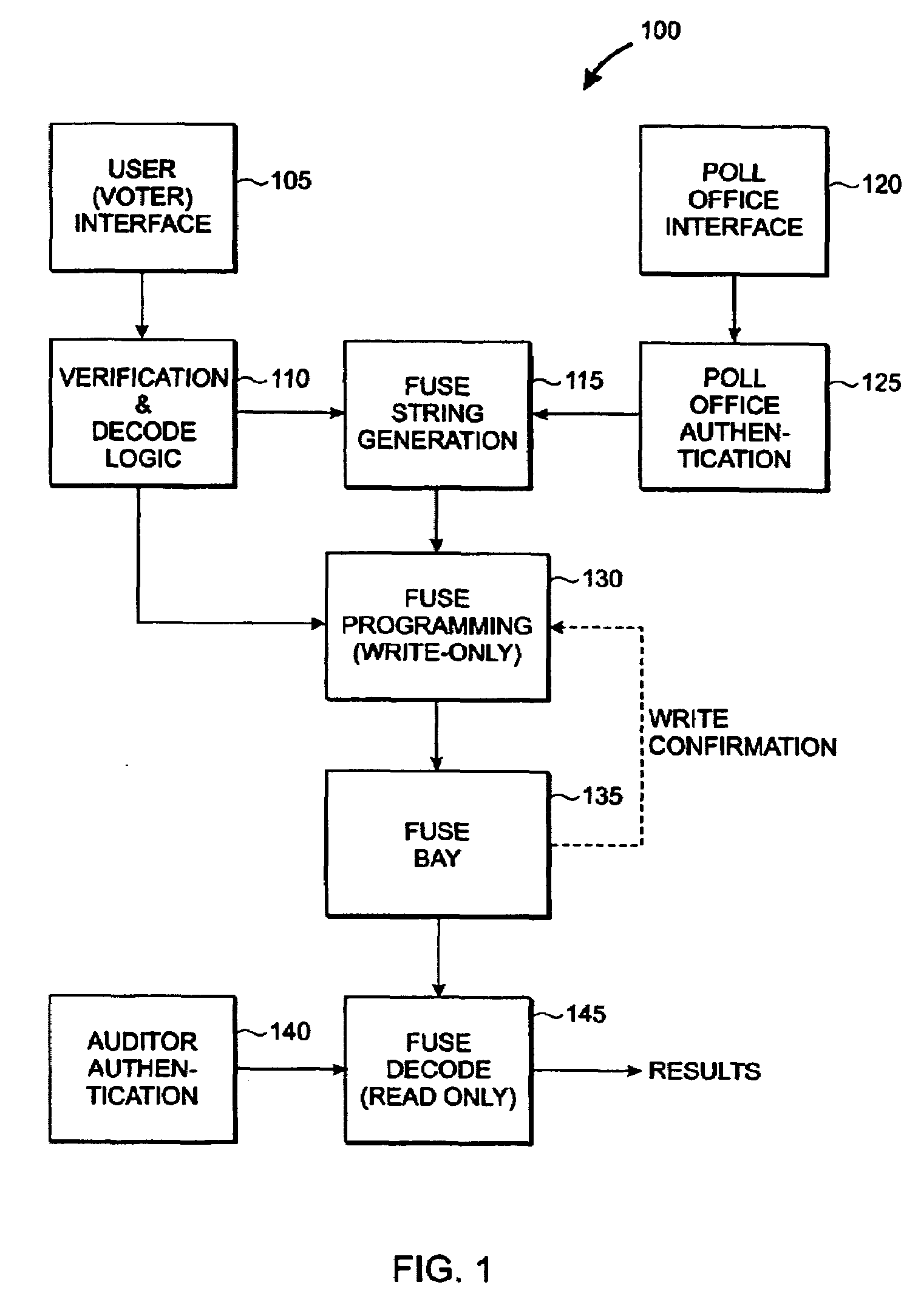
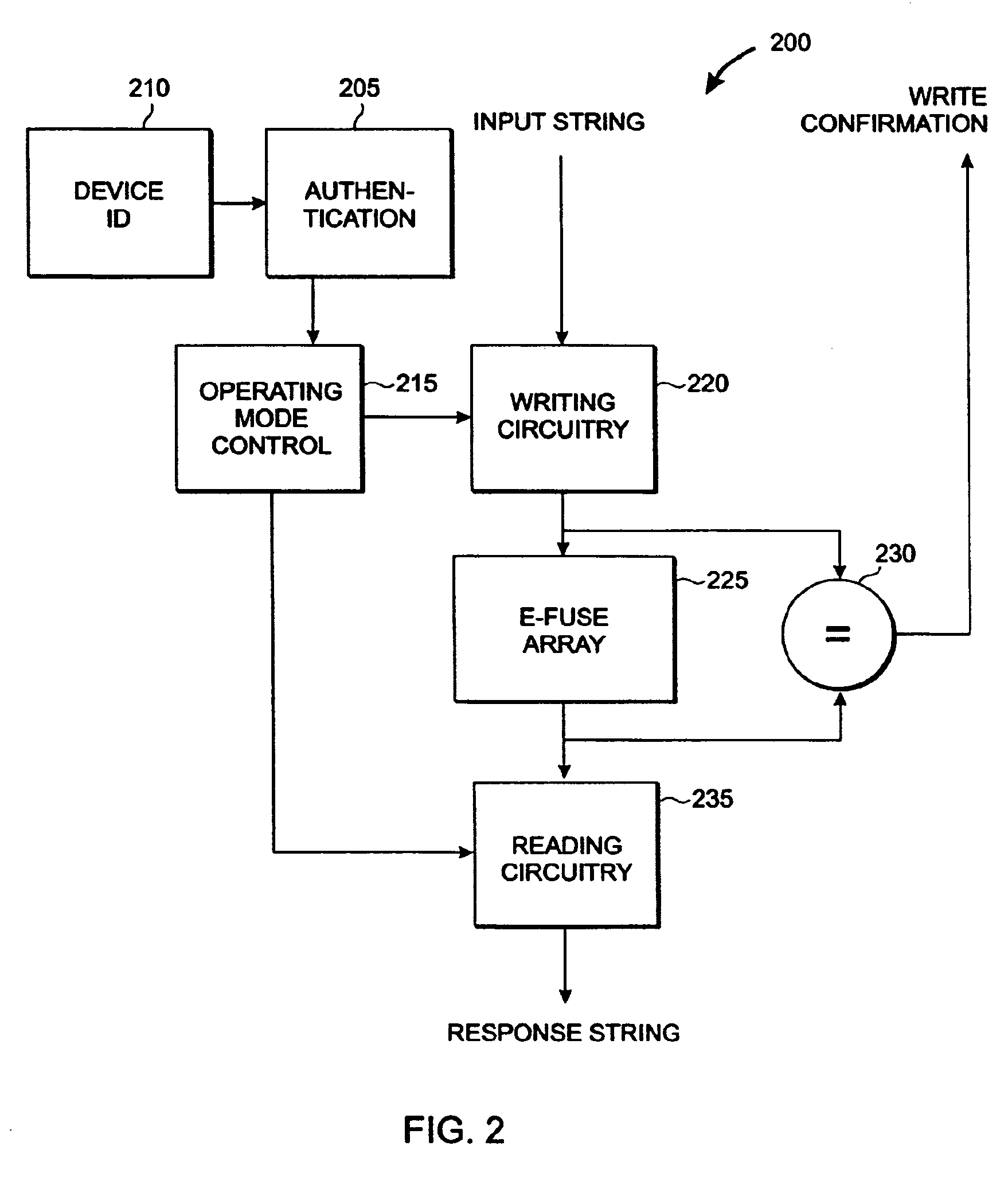
[0026]When initially enabled by poll office workers, the array starts out in its write mode. This enables vote recording onto the array. At the close of voting (or when the cartridge becomes “full”) the cartridge is switched to read mode. Once switched into read mode, it cannot be switched back to write mode. Data recorded into the array is encrypted so that only authorized poll auditing officials can read the array by decrypting the contents thereof via an appropriate encryption key. Each vote is recorded in its entirety, preferably along with voter eligibility information, thereby providing a highly secure, unalterable electronic audit trail of all votes recorded into the array.

Problems solved by technology

For all but the smallest of elections and / or ballot initiatives, the process of collecting, counting and tabulating paper ballots has proven to be tedious, time-consuming, error-prone and subject to a variety of tampering schemes.
The use of voting machines has helped to speed the process of vote counting, but these machines often suffer from a variety of shortcomings.
However, most voting machines—from the earliest mechanical machines to the latest, high-tech electronic voting machines suffer from any of a variety of shortcomings.
One of the main disadvantages of the simple lever machines is that they maintain no record of the individual votes cast—they store only totals on a per-candidate basis.
As a result, it is not possible to audit them or to “recount” individual ballots.
If the machine malfunctions and a counter wheel fails to record totals properly, there is no record from which a corrected tally can be determined.
Lever machines do not completely eliminate election fraud, either.
Occasionally, levers are mislabeled (either accidentally or deliberately).
Because of their size and weight, these machines are expensive to store and transport.
Despite the fact that lever machines were still in use in some 15% of all counties in the US, these machines are no longer manufactured, making it difficult or impossible to obtain spare parts.
Incomplete punching left many cards only “dimpled” or partially perforated, and a variety of other problems resulted in many complaints of improperly recorded vote totals.
Because these punched cards were counted by electronic means (typically by optical scanning or by sense wires in punched-card readers), improperly or partially perforated cards could register incorrectly.
They are also highly vulnerable to tampering.
While this may represent a significant cost savings to local election authorities, the portability of such devices makes them relatively easy to steal and manipulate.
Although actual incidents of vote tampering may be relatively rare, the implications of successful vote tampering are enormous, especially if the practice becomes widespread.
If such a practice is ignored and becomes widespread, the outcomes of elections can be affected.
Most fully-automated electronic voting systems are programmed to notify the voter that an undervote or overvote has occurred and will not permit the vote to be entered until the problem is corrected.
Occasionally, however, programming errors occur and overvotes / undervotes are recorded, possibly misrepresenting the voter's intention.
On paper ballot systems, an improperly filled out from may cause the ballot counting device (e.g., optical scanning system) to reject the ballot, effectively negating that ballot.
Even worse, a programming error could cause valid ballots to be rejected while improperly filled-out ballots are recorded.
In a secret ballot, there is no way to know how any one voter cast his / her ballot, frustrating coercion and leaving voters with no record of their ballot to exchange for payment.
Interpretation Problems: On some ballots, there are rules as to how the ballot is to be cast.
Depending upon the complexity of the rules and the clarity of the voter instructions, such ballot choices can be confusing, leading to significant questions of interpretation when tallying vote totals.
However, some voting systems (e.g., the well known lever system) provide no effective means for recounting, because there is no audit trail of individual votes from which to reconstruct the vote totals.
However, there is great concern over the nature of the audit trail information.
In fully electronic systems, the validity of an electronically recorded audit trail is the subject of considerable debate, since the recording media can be altered and in the event of a voting system failure, there may be no way to guarantee the integrity of the electronic audit record.
Unless a system can be demonstrated to provide a virtually flawless audit record (even in the event of a system failure), lack of confidence in the validity of audit trail information can render such a system useless.
One of the biggest problems with electronic voting systems is their dependence upon conventional electronic recording media.
While strong encryption mechanisms may be able to prevent “snooping” and may effectively control access to election data, it may not be possible to prevent damage to the vote recording media and / or audit record.
In the event of a discrepancy, it is difficult to determine which record is correct.
Further, the possibility of destruction, loss or defacing of the paper record raises many of the old concerns about paper ballot tampering.

Method used


Image

  • Secure electronic voting device
  • Secure electronic voting device
  • Secure electronic voting device

Examples


Embodiment Construction

[0040]According to the invention, a write-once vote recording medium is employed to record individual votes, providing both an audit trail and a record of vote totals. This write-once memory has several characteristics that make it uniquely suited for recording of vote information. Specifically, the vote recording medium:[0041]acts as a write-once memory, which once programmed cannot be altered.[0042]has two distinct modes of operation, “write mode” and “read mode”[0043]when in “write mode”, the medium cannot be read[0044]when in “read mode”, the medium cannot be written[0045]once switched into “read mode” the medium cannot be switched back into “write mode”

[0046]Preferably, the vote recording medium is an e-fuse array (similar in nature to older “fusible-link” PROMs). Also, the vote recording medium preferably embodies a hardware confirmation mechanism for verifying that a requested write operation was successfully and accurately executed. This confirmation mechanism provides write...


PUM


Abstract

A secure device for electronic voting employs a write-once vote-recording medium. The medium has an initial writing mode in which data can be written but not read and a subsequent reading mode whereby data can be read but writing is permanently disabled. Once switched from the writing mode to the reading mode, it cannot be switched back. A hardware mechanism provides successful write confirmation The medium can be installed like a cartridge into a vote-recording device. The voting device provides encryption / authorization that combines polling parameters with voter information to produce a “fuse string”. For each vote, a fuse string is written to the array. The poll is “closed” by switching the medium to “read” mode, preventing further modification or tampering. To read out the results of the poll, an auditor enters “password” information to decode / decrypt the recorded information.

Description

TECHNICAL FIELD[0001]The present invention relates to voting devices, and more particularly to devices for registering votes (ballots) electronically.BACKGROUND OF THE INVENTION[0002]Voting machines are well known, and have been in use for over a century in the United States. Such machines are intended to speed the vote counting process and to eliminate a variety of problems inherent in voting by paper ballot. For all but the smallest of elections and / or ballot initiatives, the process of collecting, counting and tabulating paper ballots has proven to be tedious, time-consuming, error-prone and subject to a variety of tampering schemes. The use of voting machines has helped to speed the process of vote counting, but these machines often suffer from a variety of shortcomings. For example, simple mechanical lever voting machines of various types have been in use in parts of the United States since 1892. Voters pull levers corresponding to the candidates for whom they wish to cast a vo...

Claims


Application Information

Patent Timeline
Patent Type & Authority Patents(United States)
IPC IPC(8): G07C13/00
CPCG07C13/00
Inventor IYER, SUBRAMANIAN S.FREDEMAN, GREGORY J.KOTHANDARAMAN, CHANDRASEKHARANLESLIE, ALAN
Owner GOOGLE LLC
Learn More