Image-reading apparatus

a technology of image-reading apparatus and led light, which is applied in the direction of discharge tube/lamp details, optical elements, instruments, etc., can solve the problems of poor linear reading efficiency, limited number of leds to be increased in order to enhance illumination intensity, and difficulty in efficiently guiding light to the surface of documents, etc., to prevent the reading of wrinkles on documents, correct reading, and efficient light emitted

Inactive Publication Date: 2006-08-01
MITSUBISHI ELECTRIC CORP
View PDF9 Cites 41 Cited by
  • Summary
  • Abstract
  • Description
  • Claims
  • Application Information

AI Technical Summary

Benefits of technology

[0011]The present invention relates to an image-reading apparatus, and an object of the invention is to provide such a shape of a light-guiding body that can guide light emitted from a LED while reflecting such light under conditions which satisfy total reflection as much as possible within the light-guiding body, to thereby improve the light intensity on the surface of a document in the shorter axial direction (i.e., the sub-scanning direction), and also that has such an optimized shape of a light-incoming face as to make it possible to control the angle of light fluxes in the longer axial direction (i.e., the main scanning direction) to thereby illuminate the surface of the document with light having an uniform intensity distribution. Another object of the present invention is to prevent reading of a wrinkle on the surface of the document by providing a reflecting member.
[0013]The image-reading apparatus according to the present invention makes it possible to efficiently guide light emitted from a light source to an objective reading region. In addition, since illuminating light is uniformly distributed on the surface of a document, an image of the document can be correctly read. Further, it becomes possible to prevent the reading of wrinkles on the document by providing a reflecting member.

Problems solved by technology

However, this apparatus has a defect in that, since the surface of the hollow light-guiding body is colored white, most of light is diffused, and therefore, it is difficult to efficiently guide light to the surface of a document.
However, this image-reading apparatus has a problem in that the number of LEDs to be increased in order to enhance the intensity of illumination is limited, because light from LEDs are led to the light-guiding body, only from the side wall or the center of the base of the light-guiding body: i.e., the opening of the light-guiding body for introducing LED is small.
As a result, the efficiency of utilizing illuminating light is poor in case of linear reading.
However, this apparatus has problems in that the shapes of lenses arrayed are complicated, and also that high accuracy is demanded for production of the apparatus.
The illuminating optical systems of the existing image-reading apparatuses which comprise the inventions disclosed in the above publications have problems in that the illumination angles are polarized because light fluxes directly illuminate the surfaces of documents from the light-guiding means, and therefore that the wrinkles on the surfaces of the documents cast their shadows, in other words, undesirably, the reading optical systems read such shadows.

Method used


Image

  • Image-reading apparatus
  • Image-reading apparatus
  • Image-reading apparatus

Examples


embodiment 2

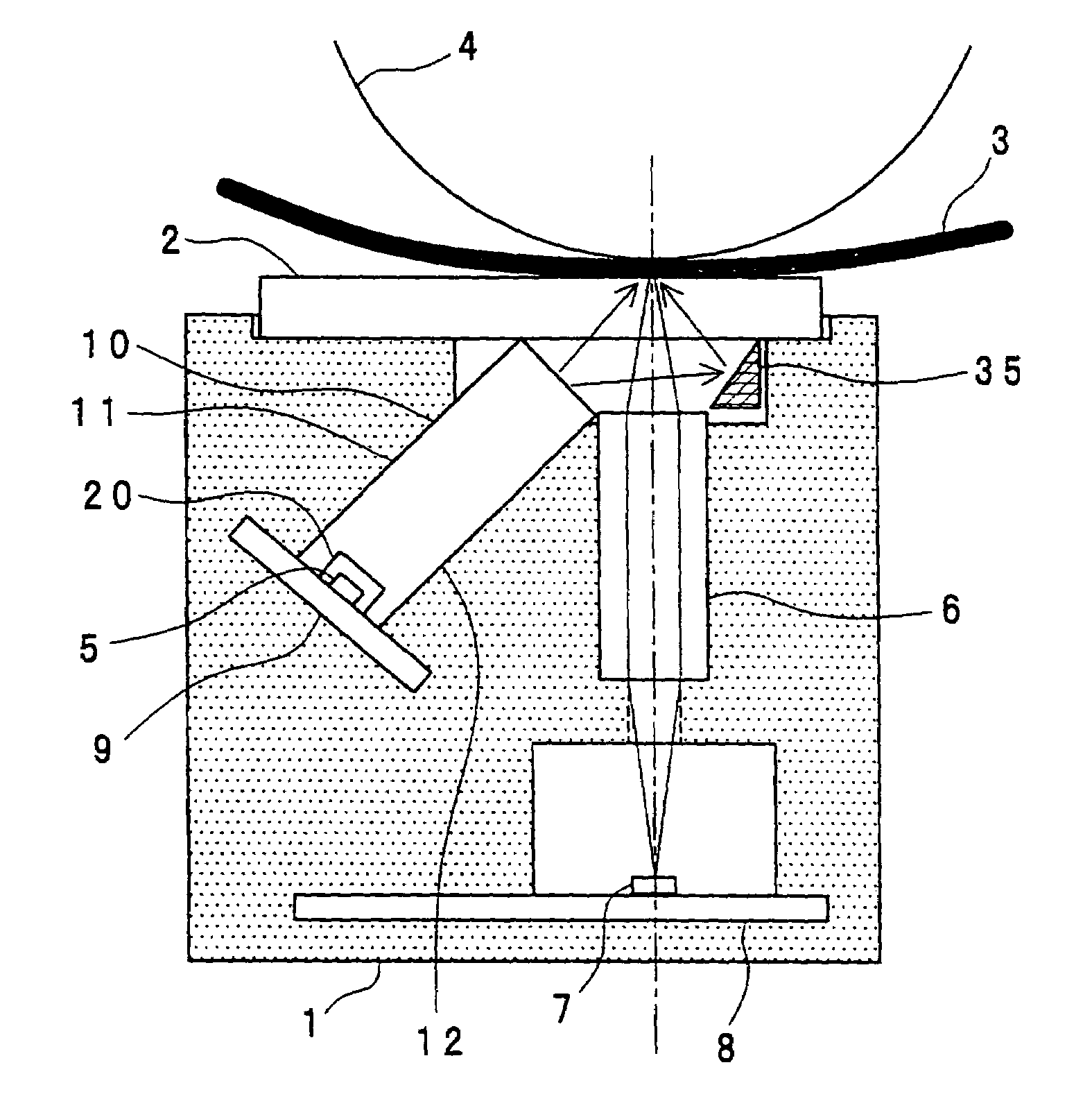
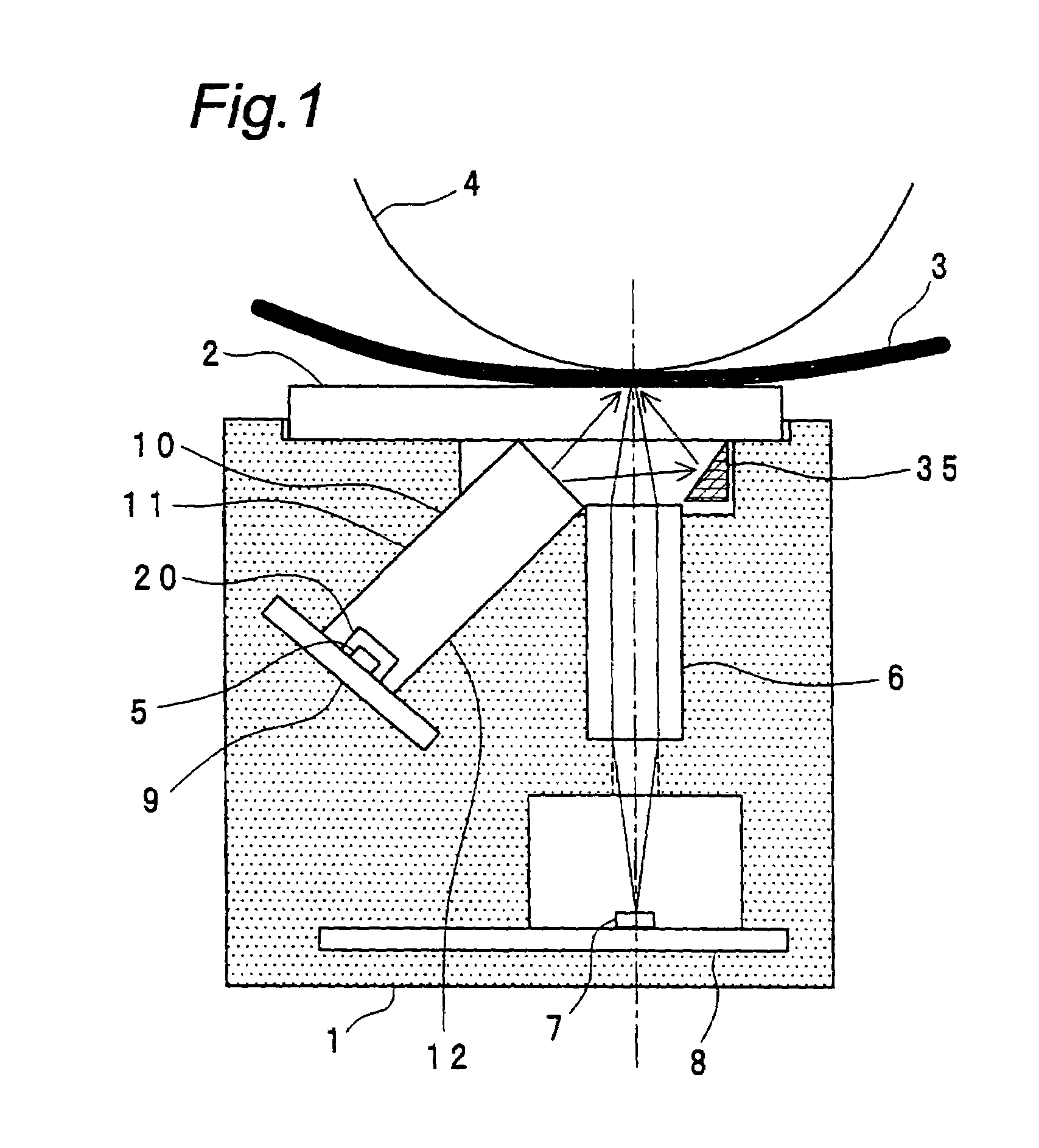
[0046]FIG. 4 shows a sectional view of an image-reading apparatus according to the second embodiment of the present invention, taken along the shorter axial direction thereof (i.e., the sub-scanning direction). The second embodiment shown in FIG. 4 is practically the same one as the first embodiment shown in FIG. 1. Therefore, the description of the same parts is omitted by denoting them with the like reference numerals.

[0047]In the image-reading apparatus according to the second embodiment, the light-guiding means (10) has a ninth face (21) and a tenth face (22) between the first face (11) and the light outgoing face thereof and between the second face (12) and the light outgoing face thereof, respectively. The ninth face (21) and the tenth face (22) form predetermined angles with the first face (11) and the second face (12), respectively.

[0048]In addition, the substrate (9) having a light source mounted thereon is not orthogonal to the first face (11) and the second face (12), unl...

embodiment 3

[0050]FIG. 5 shows a sectional view of an image-reading apparatus according to the third embodiment of the present invention, taken along the shorter axial direction thereof (i.e., the sub-scanning direction). The third embodiment shown in FIG. 5 is practically the same one as the first embodiment shown in FIG. 1 or the second embodiment shown in FIG. 4. Therefore, the description of the same parts is omitted by denoting them with the like reference numerals.

[0051]In the image-reading apparatus according to the third embodiment, the light source (5) is disposed on the same substrate together with the line sensor IC (7), by adjusting the lengths and angles of the first face (11), the second face (12), the ninth face (21) and the tenth face (22) of the light-guiding means (10). In other words, the substrate having the light source mounted thereon and the substrate (8) having the sensor mounted thereon are formed integrally with each other.

[0052]By doing so, the number of the component...

embodiment 4

[0061]FIG. 10 shows a sectional view of a light-guiding means (10) to be used in an image-reading apparatus according to the fifth embodiment of the present invention, taken along the shorter axial direction of the light-guiding means (i.e., the sub-scanning direction). FIG. 11 shows a sectional view of a light-guiding means (10) as a comparative example, taken along the shorter axial direction thereof.

[0062]As shown in FIG. 11, the light-guiding means (10) is formed having a section in the shape of a simple rectangular parallelopiped (or a part thereof) at and around the substrate (9) having the light source mounted thereon, when taken along the shorter axial direction thereof. Particularly in such a case, when light from the light source (5) enters the light-guiding means (10), parts of the light fluxes which reach the first face (11) and the second face (12) of the light-guiding means (10) have angles smaller than the angles which satisfy the total reflection condition (about 45°...


PUM


Abstract

There is provided such a shape of a light-guiding body that can guide light emitted from a LED while reflecting such light under conditions which satisfy total reflection as much as possible within the light-guiding body, to thereby improve the light intensity on the surface of a document in the shorter axial direction (i.e., the sub-scanning direction), and also, the light-guiding body has such an optimized shape of a light-incoming face that makes it possible to control the angle of light fluxes in the longer axial direction (i.e., the main scanning direction) to thereby illuminate the surface of the document with light having an uniform intensity distribution. Further, a reflecting member is provided at a position opposite the light outgoing face of the light-guiding body so as to improve the efficiency of illuminating an objective image-reading region on the surface of the document.

Description

CROSS-REFERENCE TO RELATED APPLICATION[0001]The present application claims the benefit of patent applications No. 2003-353282 filed in Japan on Oct. 14, 2003 and No. 2004-60125 filed in Japan on Mar. 4, 2004, the subject matter of which is hereby incorporated herein by reference.BACKGROUND OF THE INVENTION[0002]1. Field of the Invention[0003]The present invention relates to an image-reading apparatus, and particularly to an illuminating optical system thereof.[0004]2. Description of the Related Art[0005]In the image sensors of a facsimile, copying machine, scanner, etc. which read reflected light from documents to be read, light-emitting diodes (or LED) are widely used as illuminating optical systems.[0006]The invention disclosed in JP-A-2001-136341 relates to the basic structure of a color-sequentially reading type contact image sensor, and the invention provides an image sensor which shows uniform output levels of red, green and blue and has a high sensitivity. The image-reading a...

Claims


Application Information

Patent Timeline
Patent Type & Authority Patents(United States)
IPC IPC(8): H04N1/40G02B6/00G02B6/42H04N1/028H04N1/031H04N1/12H04N1/192
CPCG02B6/4298H04N1/02815H04N1/02835H04N1/0285H04N1/02855H04N1/02865H04N1/0318H04N1/192G02B6/0001H04N2201/03145H04N2201/03129H04N2201/0312H04N2201/03116H04N2201/03112H04N1/1215H04N2201/03104H04N2201/03125H04N2201/03141
Inventor OKAMOTO, TATSUKISATO, YUKIOKAWANO, HIROYUKISONO, ATSUHIROARIMOTO, HIRONOBUMATSUMOTO, TOSHIOOTA, AKIRA
Owner MITSUBISHI ELECTRIC CORP
Why Eureka
Try Eureka