
Electrical card connector including a locking mechanism

Inactive Publication Date: 2007-09-18
JESS-LINK PRODUCTS
View PDF4 Cites 24 Cited by
  • Summary
  • Abstract
  • Description
  • Claims
  • Application Information

AI Technical Summary

Benefits of technology

[0007]One particular aspect of the present invention is to provide an electrical connector that includes a locking element on the shell body. The locking element fits with locking structure located on the insulating body so as to make the shell body be firmly locked with the insulating body. The present invention also has a flexible-locking part on the insulating body. By fitting the conducting metal flake located on the flexible-locking part with the locking element, the shell body is locked with the insulating body and has a grounding effect.
[0008]Furthermore, the present invention has a pivoting concave ditch on the insulating body and has a blocking element on the shell body, and the pivoting concave ditch matches the blocking element to produce a blocking effect which prevents the shell body from being rotated outward and damaging the structure of the shell body. Moreover, the shell body has a convex point. When the shell body is locked with the insulating body, the grounding is good via contacting the convex point with the flexible-locking structure.

Problems solved by technology

The shell body does not rotate to the outside of the insulating body and damage the structure of the shell body.

Method used


Image

  • Electrical card connector including a locking mechanism
  • Electrical card connector including a locking mechanism
  • Electrical card connector including a locking mechanism

Examples


Embodiment Construction

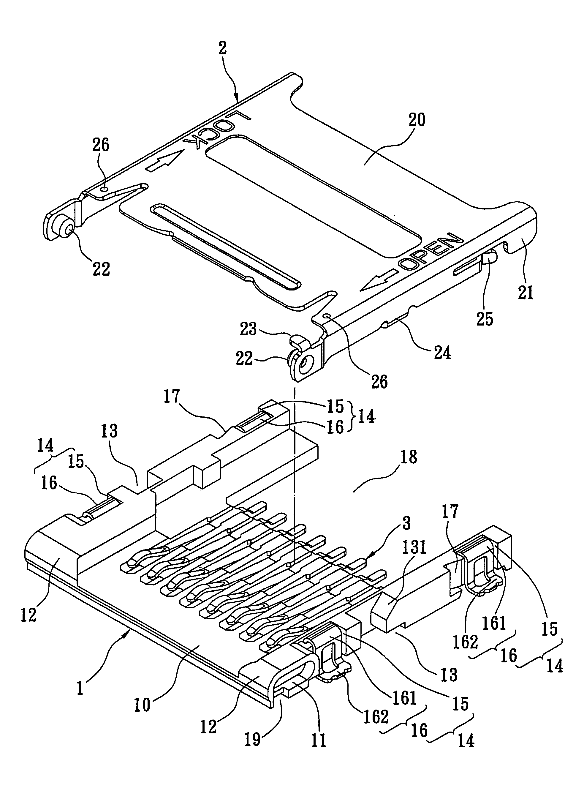
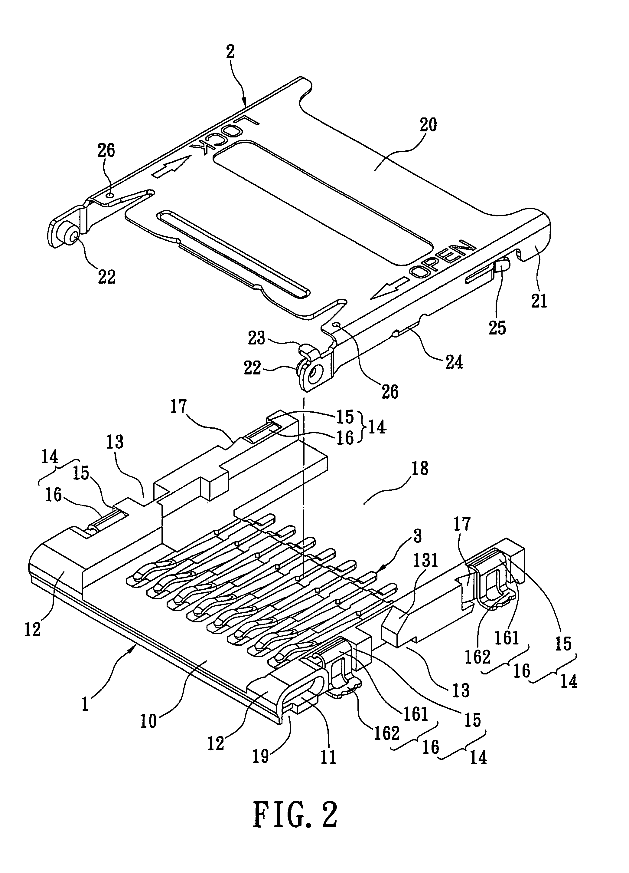
[0021]Reference is made to FIG. 2, which shows an exploded perspective view of the electrical connector of the present invention. The electrical connector includes an insulating body 1 and a shell body 2.

[0022]The electrical connector includes an insulating body, and a shell body. The insulating body includes a body, pivoting concave ditches 11 located at two sides of end of the body 10 and formed along the horizontal direction, and circular rotating angles 12 located at a top rim of two sides of the end of the body 10. The body 10 receives a plurality of conducting pins 3.

[0023]The shell body 2 includes a top wall 20, side walls 21 formed at sides of the top wall 20, pivoting convex columns 22 respectively formed at the end of the two sides of the side wall 21 and facing inward, and a blocking element 23 located at a top rim of one of the side walls 21 and contacting the circular rotating angle 12.

[0024]The insulating body 1 further includes a locking part 13 and a guiding angle 13...


PUM


Abstract

An electrical connector includes an insulating body, and a shell body. The insulating body includes a body, pivoting concave ditches located at two sides of end of the body and formed along horizontal directions, and circular rotating angles located at the top rim of the two sides of the end of the body. The body receives a plurality of conducting pins. The shell body includes a top wall, side walls, pivoting convex columns, and a blocking element. The pivoting convex column is located in the pivoting concave ditch. By moving the pivoting convex column in the pivoting concave ditch, the shell body moves. By contacting the blocking element with the arc of the circular rotating angle, when the shell body rotates to a specified angle with the insulting body, the shell body moves along the side wall of the shell body.

Description

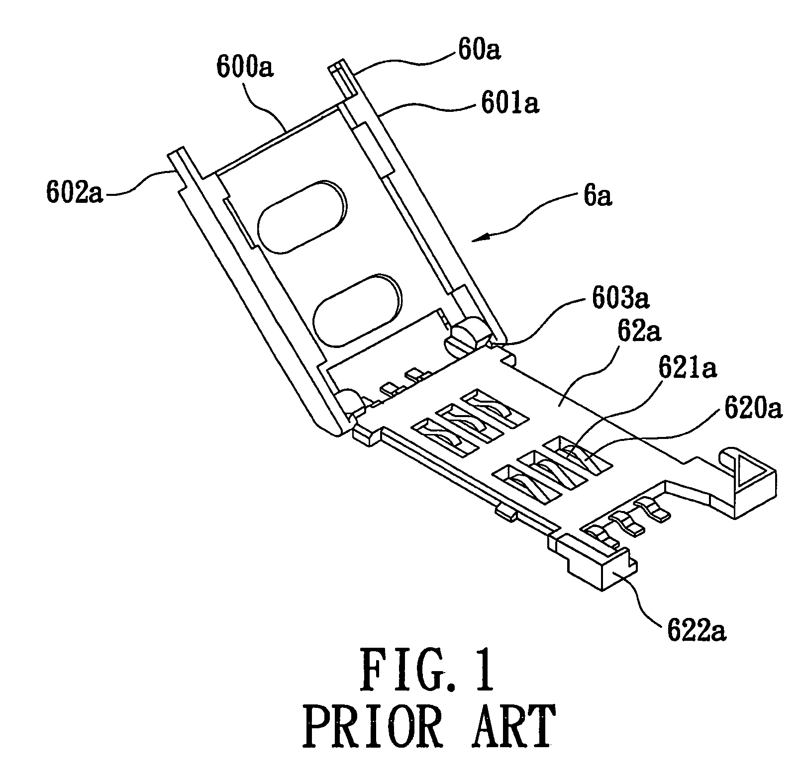
BACKGROUND OF THE INVENTION[0001]1. Field of the Invention[0002]The present invention relates to an electrical connector. In particular, this invention relates to an electrical connector that is applied in information and communication devices.[0003]2. Description of the Related Art[0004]As information technology has developed and progressed, personal information and communication devices (such as cell phones or personal computers) have become more and more popular. Furthermore, as communication and Internet technology has changed with each passing day, cell phones have become the most popular communication tool. A SIM card in a cell phone is used for identifying the user when they electrically connect with the circuit board via a connector.[0005]Reference is made to FIG. 1, which shows a perspective view of the connector of the prior art. The connector includes an upper cover 60a, and a contacting-point module 62a. The upper cover 60a includes a metal cover body 600a, and clipping ...

Claims


Application Information

Patent Timeline
IPC IPC(8): H01R13/62
CPCG06K7/0021G06K13/085
Inventor CHEN, CHENG-YI
Owner JESS-LINK PRODUCTS
Learn More