Welding tank cart system

a technology of welding tank and cart system, which is applied in the field of welding carts, can solve the problems of unnecessary movement of welding tanks during transportation, inconvenient storage space for various types of welding related items, and inconvenient transportation of welding tanks and welding supplies, so as to achieve the effect of not being prone to tipping

Inactive Publication Date: 2007-09-25
HOHRMAN HARLAN W
View PDF27 Cites 41 Cited by
  • Summary
  • Abstract
  • Description
  • Claims
  • Application Information

AI Technical Summary

Benefits of technology

The invention relates to a welding tank cart system with two main technical features: one is its use of a chain tightening system which makes it easy to connect the chains between different welding tanks, and another is its stability design which prevents the cart from tilting or falling over during usage.

Problems solved by technology

The technical problem addressed by this patent is how to create a better welding cart that can efficiently transport welding tanks and supplies without requiring excessive effort on the part of the user. Current carts tend to be bulky, unstable, and require too much force to move. This new design offers a solution to improve efficiency when moving welding equipment.

Method used


Image

  • Welding tank cart system
  • Welding tank cart system
  • Welding tank cart system

Examples


Embodiment Construction

A. Overview

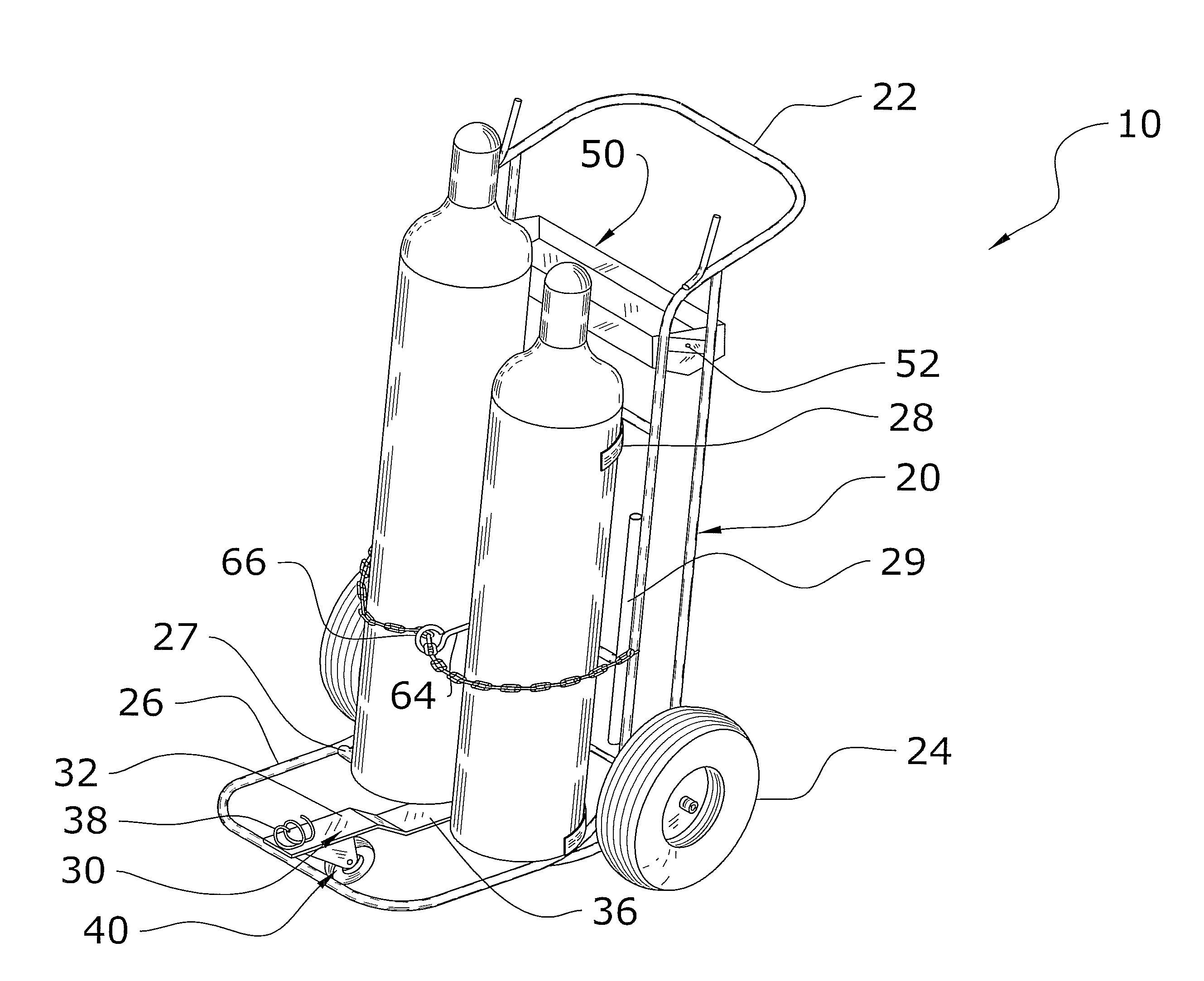
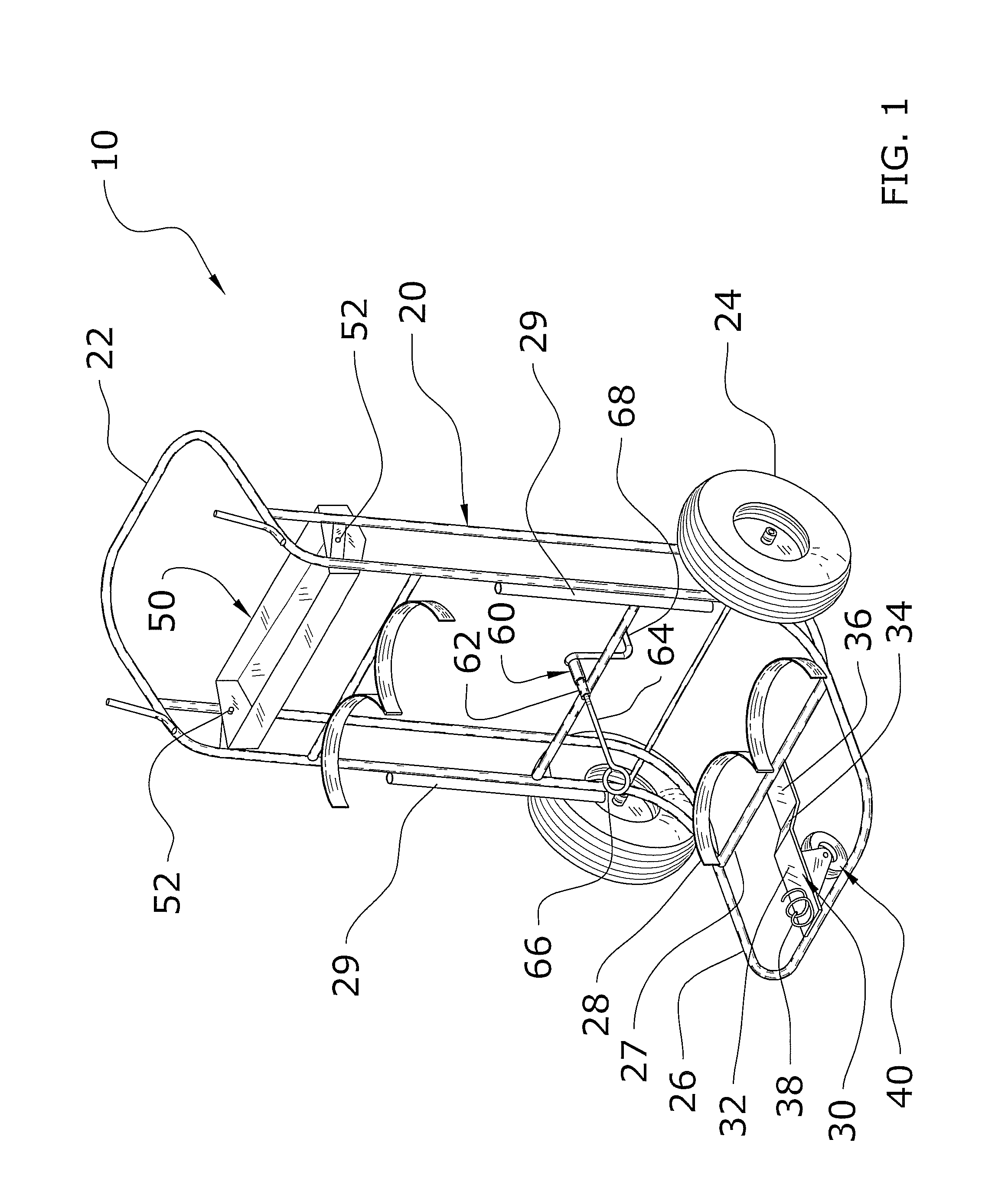
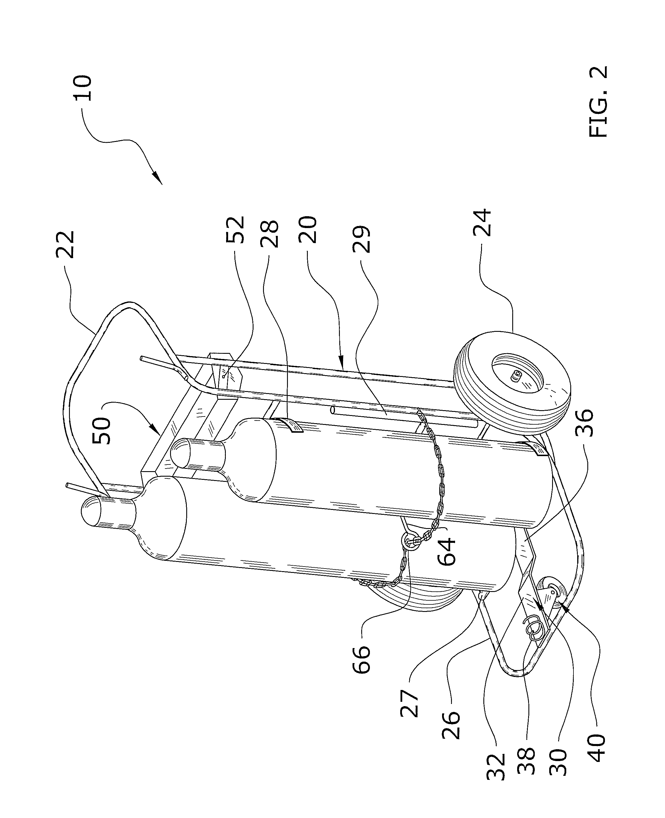
[0037]Turning now descriptively to the drawings, in which similar reference characters denote similar elements throughout the several views, FIGS. 1 through 9 illustrate a welding tank cart system 10, which comprises a frame 20, a pair of side wheels 24, a wheel support 30 connected to the frame 20, and a front wheel 40 connected to the wheel support 30, wherein the front wheel 40 is comprised of a swivel wheel. A tray 50 is pivotally connected within the frame 20 to provide for self-leveling regarding of the attitude of the frame 20. A chain crank 60 is connected to the frame 20 for tightening a chain structure 12 about the welding tanks.

B. Frame

[0038]FIGS. 1 and 3 best illustrate an exemplary frame 20 for the present invention. It can be appreciated that the frame 20 illustrated in the attached drawings is not intended to limit the scope of the present invention. The frame 20 may be comprised of any structure capable of supporting and transporting a pair of welding tank...


PUM


Abstract

A welding tank cart system for providing efficient transportation of welding tanks and welding supplies. The welding tank cart system includes a frame, a pair of side wheels, a wheel support connected to the frame, and a front wheel connected to the wheel support, wherein the front wheel is comprised of a swivel wheel. A tray is pivotally connected within the frame to provide for self-leveling regarding of the attitude of the frame. A chain crank is connected to the frame for tightening a chain structure about the welding tanks.

Description


Claims


Application Information

Patent Timeline
Owner HOHRMAN HARLAN W
Why Eureka
Try Eureka