Golf club head

a golf club and sole portion technology, applied in golf clubs, sport apparatus, etc., can solve the problems of prone to increase the amplitude of vibration produced at the time of shots, partially insufficient rigidity, etc., and achieve high rigidity in the toe-to-heel direction, increase the carrying of the ball, and high rigidity of the sole portion

a golf club and sole portion technology, applied in golf clubs, sport apparatus, etc., can solve the problems of prone to increase the amplitude of vibration produced at the time of shots, partially insufficient rigidity, etc., and achieve high rigidity in the toe-to-heel direction, increase the carrying of the ball, and high rigidity of the sole portion

US7273423B2Inactive Publication Date: 2007-09-25BRIDGESTONE SPORTS

Image

  • Golf club head
  • Golf club head
  • Golf club head

Examples


Embodiment Construction

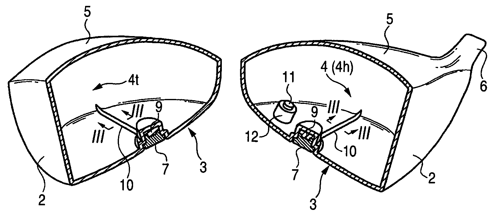
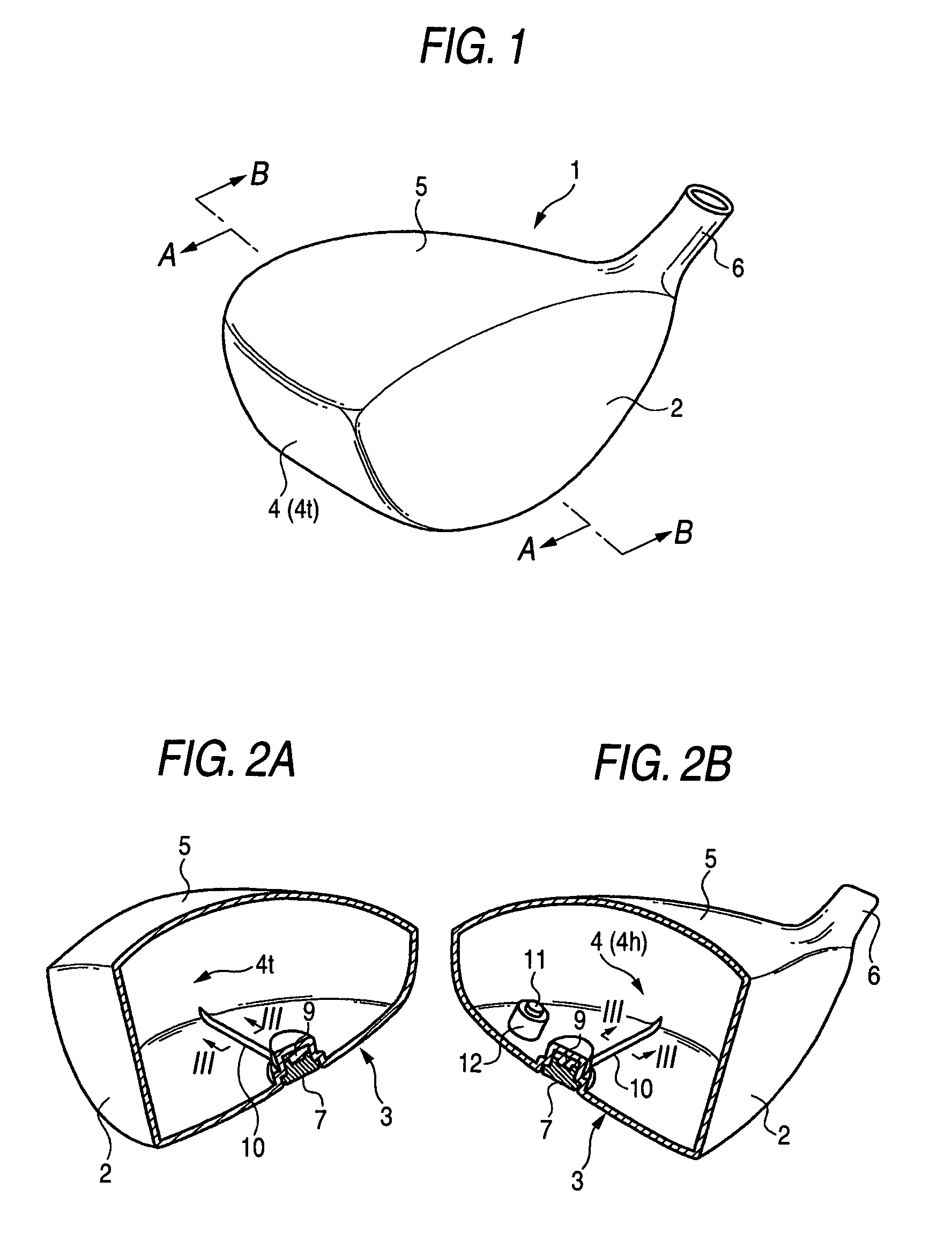
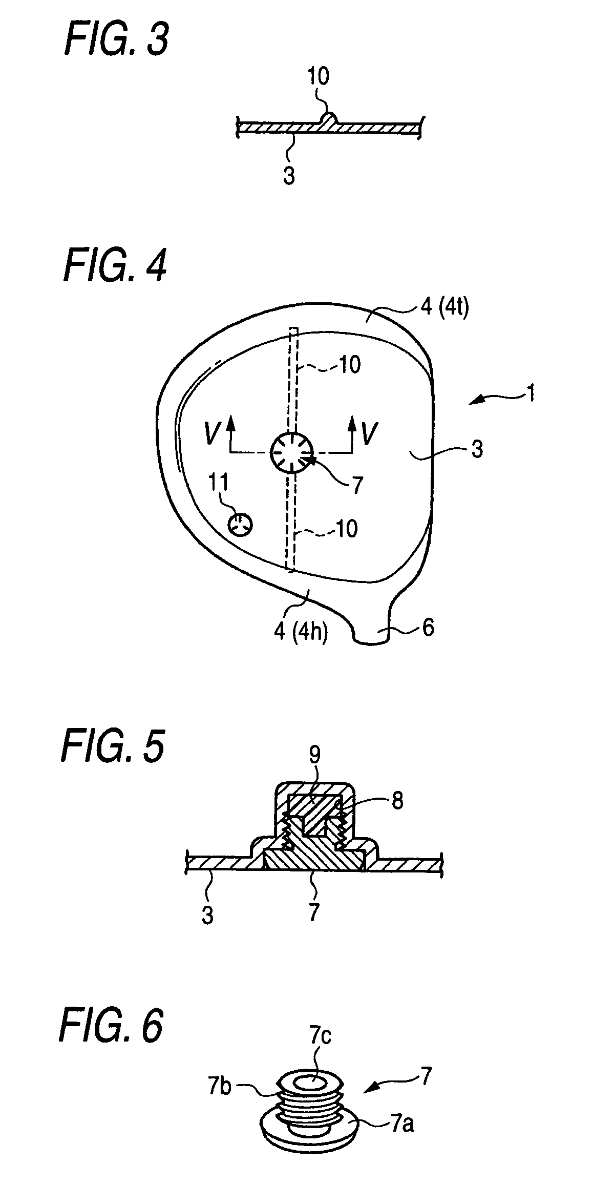
[0034]The preferred embodiments of the present invention will be described below with reference to the accompanying drawings. FIG. 1 is a perspective view of a golf club head according to an embodiment of the invention. FIGS. 2A and 2B are perspective views, in cross section, of the golf club head taken along the line A-A and the line B-B as shown in FIG. 1. FIG. 3 is a cross-sectional view of the golf club head taken along the line III-III as shown in FIG. 2. FIG. 4 is a bottom view of the golf club head. FIG. 5 is a cross-sectional view of the golf club head taken along the line V-V as shown in FIG. 4. And FIG. 6 is a perspective view of a weight material.

[0035]This golf club head 1 is of wood type and has a hollow shell structure including a face portion 2, a sole portion 3, a side portion 4, a crown portion 5 and a hosel portion 6.

[0036]The face portion 2 is a plane for hitting the ball, and provided with grooves (score lines), not shown. The sole portion 3 makes up a bottom fac...


PUM


Abstract

To provide a golf club head in which a sole portion has a high rigidity. A weight material is mounted near a central part of the sole portion in the fore-to-aft direction, and a rib extends in the toe-to-heel direction. Since the sole portion has high rigidity in the toe-to-heel direction, there is less deformation of the head in the toe-to-heel direction when hitting the ball, thereby suppressing the vibration of the sole portion. An elastic body is filled in a recess portion and closely contacted with the weight material, whereby the vibration of the sole portion is absorbed by the elastic body.

Description

BACKGROUND OF THE INVENTION[0001]1. Field of the Invention[0002]The present invention relates to a hollow golf club head, and particularly to a golf club head being of a wood type or similar type thereto.[0003]2. Description of the Related Art[0004]As wood-type golf club heads such as drivers and fairway woods, metallic heads of a hollow shell structure are widely in use. Generally, the hollow wood-type golf club head has a face portion for hitting a ball, a crown portion constituting an upper surface portion of the golf club head, a sole portion constituting a bottom surface portion of the golf club head, a side portion constituting side surface portions on the tow side, the rear side, and the heel side of the golf club head, and a hosel portion. A shaft is inserted into the hosel portion, and is fixed by an adhesive agent or the like. It should be noted that golf clubs called utility clubs are also commercially available on the market in large numbers, and various golf clubs havin...

Claims


Application Information

Patent Timeline
25 Sep 2007
Publication
US7273423B2
IPC
A63B53/04; A63B53/06; A63B102/32
CPC
A63B53/0466; A63B2053/0408; A63B2053/045; A63B2053/0416; A63B2053/0433; A63B2053/0491; A63B53/0408; A63B53/0416
Inventors
IMAMOTO, YASUNORI