Belt tensioner

a belt tensioner and belt technology, applied in the field of belt tensioners, can solve the problems of increasing wear, however only possible, and achieve the effect of increasing wear

Active Publication Date: 2007-09-25
LITENS AUTOMOTIVE GMBH
View PDF14 Cites 35 Cited by
  • Summary
  • Abstract
  • Description
  • Claims
  • Application Information

AI Technical Summary

Problems solved by technology

Consequently, the radial plain bearing is, however, stressed by tilting forces which cause increased wear.
This is however only possible where there is sufficient installation space available.

Method used


Image

  • Belt tensioner
  • Belt tensioner

Examples


Embodiment Construction

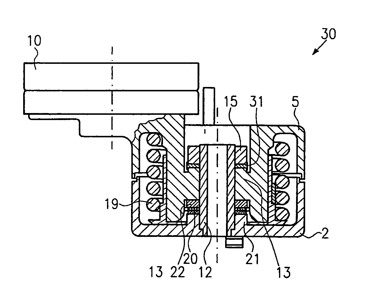
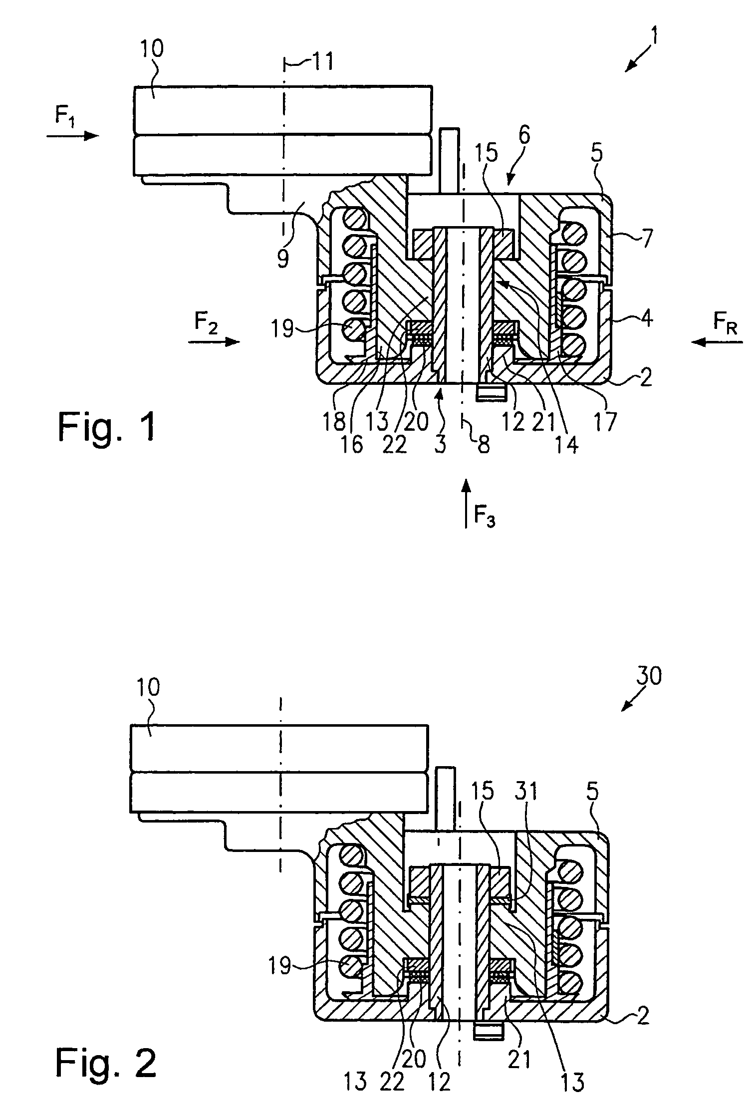
[0014]FIG. 1 illustrates a belt tensioner 1 in partial cross-section as it is used, for example, for tensioning belts in automotive vehicles. The belt tensioner 1 is however also suitable for other applications where belts, chains or other endless transmission elements need to be tensioned.

[0015]The belt tensioner 1 includes a base section 2 which is provided with a central opening 3 and cup-shaped, high-reaching walls 4 which form part of a housing. The belt tensioner 1 also includes a retainer 5, which also exhibits a central opening 6 and cup-shaped high-reaching side walls 7, whereby the walls 4 and 7 are formed such that they form the outer boundary of the belt tensioner 1 and the center lines of the openings 3 and 6 meet in a common center line 8.

[0016]The retainer 5 is also provided with a tension arm 9 which is mounted in the axial direction asymmetrically and is offset from the center line 8 on the retainer 5 and protrudes over the wall 7. An idler pulley 10 is rotationally...


PUM


Abstract

A belt tensioner with a retainer can be brought into contact with a belt via a belt support for applying a tensile force. The retainer is joined at a distance from the belt support to a radial plain bearing and it can be swivelled about the axis of rotation of the radial plain bearing, whereby the tensioning and swivel movements of the belt support occur under the action of a coil spring. For a belt tensioner of this type, which with a compact construction runs essentially wear-free, it is suggested that the retainer is subject to the action of a spring, which exerts a force (F3) essentially parallel to the axis of rotation on the retainer, the said force (F3) counteracting the force (F1) exerted by the belt on the retainer.

Description

BACKGROUND OF THE INVENTION[0001]1. Field of the Invention[0002]The invention relates to a belt tensioner of the type for automotive vehicles.[0003]2. Description of the Related Art[0004]Typical belt tensioners are known, for example from DE-A-43 27 141 or DE-A-40 10 928. These belt tensioners are employed in motor vehicles for tightening the V-belt and comprise a retainer with a tension arm, which is fitted with an idler pulley at one end, that is applied to the belt, and which is joined to a radial plain bearing at its other end. The radial plain bearing includes a bearing bush part and a bearing pin part, whereby one of the parts is fixed to the tension arm and the other part is held spatially fixed. A rotary spring in the form of a spiral coil spring is wrapped coaxially around the bearing bush and bearing pin and is held by one end on the retainer and held spatially fixed at the other end. These known belt tensioners are fitted in a state in which the bearing bush and the beari...

Claims


Application Information

Patent Timeline
Patent Type & Authority Patents(United States)
IPC IPC(8): F16H7/12F16H7/08
CPCF16H7/1218F16H2007/081
Inventor SCHONMEIER, HORSTFISCHER, MICHAEL
Owner LITENS AUTOMOTIVE GMBH
Why Eureka
Try Eureka