Prevention of charge accumulation in micromirror devices through bias inversion

a micromirror and charge technology, applied in the field of microelectromechanical systems, can solve the problems of high-voltage application, charge accumulation in the micromirror device, and the unreliable operation of the micromirror of the spatial light modulator

Active Publication Date: 2007-09-25
VENTURE LENDING & LEASING IV +1
View PDF4 Cites 26 Cited by
  • Summary
  • Abstract
  • Description
  • Claims
  • Application Information

AI Technical Summary

Problems solved by technology

The application of a high-voltage, however, has disadvantages, one of which is charge accumulation in micromirror devices.
In this situation, operation of the micromirrors of the spatial light modulator becomes unreliable.

Method used


Image

  • Prevention of charge accumulation in micromirror devices through bias inversion
  • Prevention of charge accumulation in micromirror devices through bias inversion
  • Prevention of charge accumulation in micromirror devices through bias inversion

Examples


Embodiment Construction

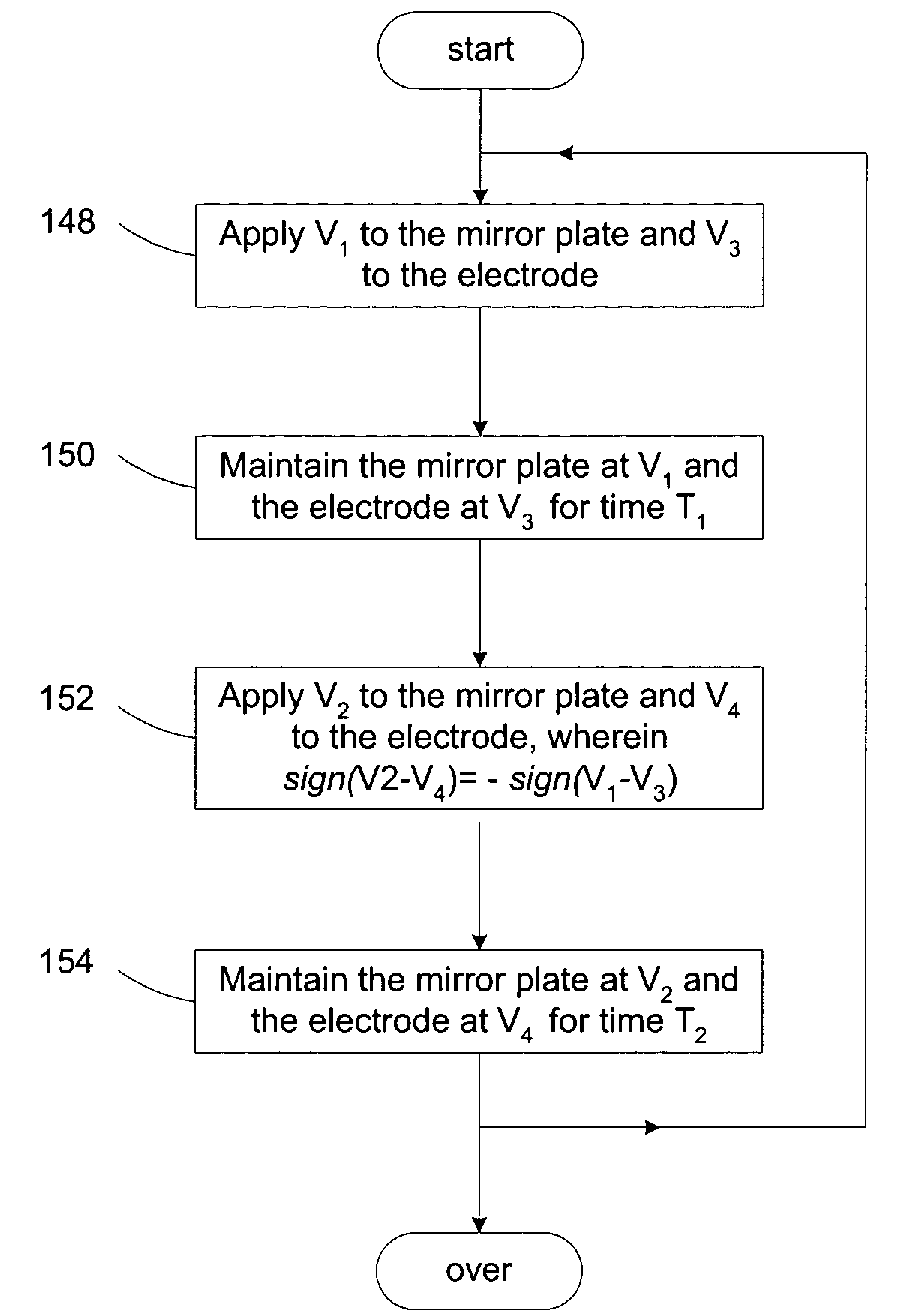
[0023]The present invention provides a method and an apparatus for preventing charge accumulation in micromirror devices by inverting the polarity of the voltage difference across the mirror plate and the electrode of the micromirror device. Specifically, a first voltage difference is established between the mirror plate and the electrode for rotating the mirror plate at one time. At another time, a second voltage difference having an opposite polarity to the first voltage difference is established between the mirror plate and the electrode for rotating the mirror plate.

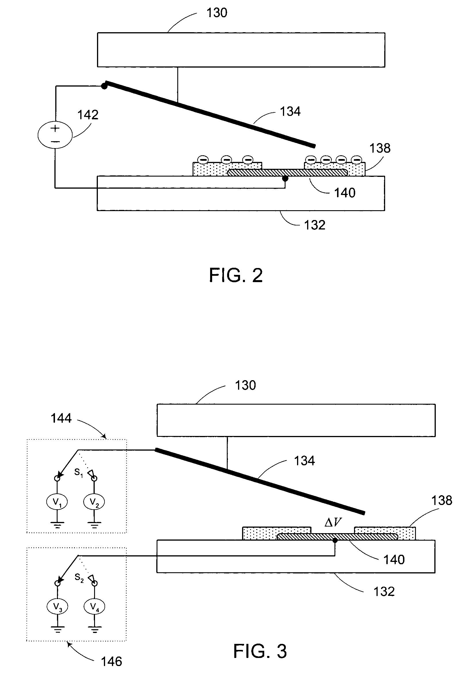
[0024]The voltage differences with different polarities can be achieved in a variety of ways, one of which is illustrated in FIG. 3. Referring to FIG. 3, the mirror plate is connected to voltage source 144 and the electrode is connected to voltage source 146. Voltage source 144 comprises two voltage states, V1 and V2. By switching the switch S1 between the two voltage states, different voltages can be applied to the ...


PUM


Abstract

Methods and apparatus are provided for preventing charge accumulation in microelectromechanical systems, especially in micromirror array devices having a plurality of micromirrors. Voltages are applied to the micromirrors for actuating the micromirrors. Polarities of the voltage differences between mirror plates and electrodes are inverted so as to prevent charge accumulation.

Description

TECHNICAL FIELD OF THE INVENTION[0001]The present invention is related generally to the art of microelectromechanical systems, and, more particularly, to methods and apparatus for preventing charge accumulation in micromirror devices.BACKGROUND OF THE INVENTION[0002]As the market demands continuously increase for display systems with higher resolution, greater brightness, lower power, lighter weight and more compact size, spatial light modulators having micromirrors and micromirror arrays have blossomed in display applications. FIG. 1 presents a simplified exemplary display system employing a spatial light modulator. In its very basic configuration, the display system comprises light source 102, optical devices (e.g. light pipe 106, condensing lens 108 and projection lens 116), display target 118 and spatial light modulator 114 that further comprises a plurality of micromirror devices (e.g. an array of micromirror devices). Light source 102 (e.g. an arc lamp) emits light through the...

Claims


Application Information

Patent Timeline
Patent Type & Authority Patents(United States)
IPC IPC(8): G09G3/36G02B26/00G09G3/00G09G3/34G09G5/00
CPCG09G3/346G09G2320/04
Inventor RICHARDS, PETER R.
Owner VENTURE LENDING & LEASING IV
Why Eureka
Try Eureka