Patient weighing system

a weighing system and patient technology, applied in the field of weighing devices, can solve the problems of cumbersome systems, requiring a substantial amount of human intervention to operate, and many sick patients are too unstable to tolerate the amount of motion these systems requir

Inactive Publication Date: 2007-10-16
PATIENTECH LLC
View PDF6 Cites 12 Cited by
  • Summary
  • Abstract
  • Description
  • Claims
  • Application Information

AI Technical Summary

Problems solved by technology

These systems are cumbersome and require a substantial amount of human intervention to operate.
Many sick patients are too unstable to tolerate the amount of motion these systems require of them.
Such a scale is expensive and therefore represents a limited resource.
These devices may not be suitable if a patient's stay in a facility extends over a prolonged period of time.
Said conditions often render a patient weak, debilitated and unable to stand without assistance, thus making it almost impossible to weigh him / her in the conventional manner (i.e., standing up on a scale).
Further, during Vascular Surgery, which may often be performed on Congestive Heart Failure patients, blood vessels leak resulting in excess body water which must be excreted by the kidneys.
Sepsis, which is a condition wherein bacteria is found in the blood stream, also results in leakage of water from blood vessels into tissues necessitating treatment with additional fluid in order to maintain blood pressure.
Lastly, the treatment of Extreme Diarrhea and Irritated Intestines often require massive amounts of fluid resuscitation to treat dehydration.
These systems, while having an electrical device mounted in a patient's bed or adhered to a patient's sheet, are used for sensing the whereabouts of the patient and are not used for weighing the patient.

Method used


Image

  • Patient weighing system
  • Patient weighing system
  • Patient weighing system

Examples


Embodiment Construction

[0029]The aspects, features and advantages of the present invention will become better understood with regard to the following description with reference to the accompanying drawing(s). What follows are preferred embodiments of the present invention. It should be apparent to those skilled in the art that these embodiments are illustrative only and not limiting, having been presented by way of example only. All the features disclosed in this description may be replaced by alternative features serving the same purpose, and equivalents or similar purpose, unless expressly stated otherwise. Therefore, numerous other embodiments of the modifications thereof are contemplated as falling within the scope of the present invention as defined herein and equivalents thereto.
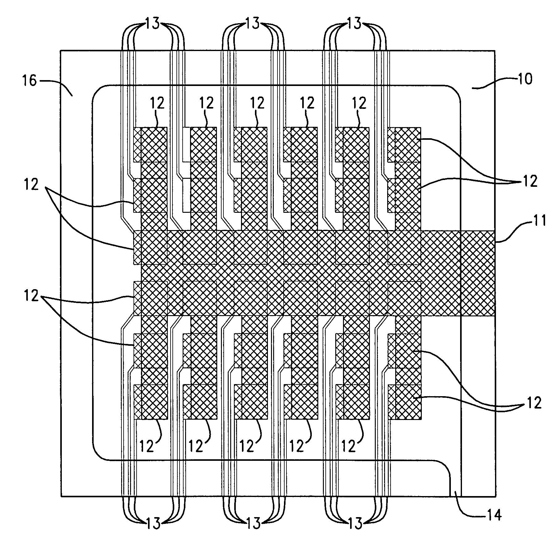
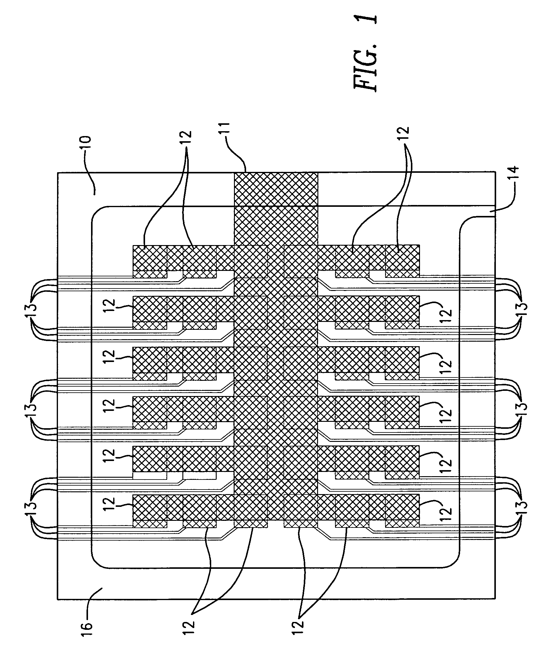
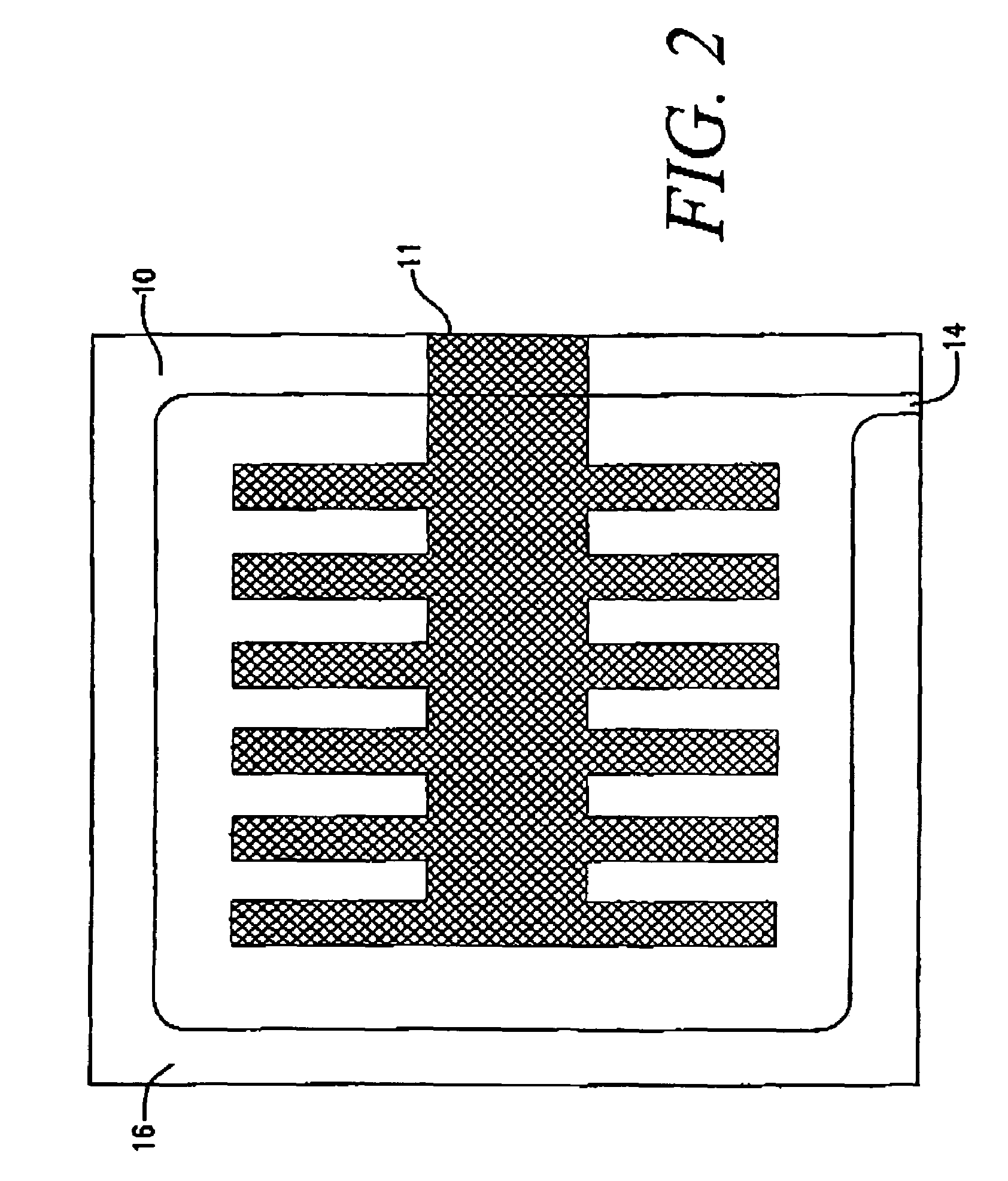
[0030]FIGS. 1–3

[0031]As shown in FIGS. 1–3, the present invention embodies a technique which combines printed contact switches and the measurement of pressure inside a closed bladder 10. The bladder 10 is an inflatable devic...


PUM


Abstract

Provided herein are exemplary embodiments of a weighing device comprising a bladder and a plurality of contact switches printed on the bladder. The bladder comprises a top and a bottom sheet of a suitable non porous material. The contact switches are made by printing a conductive pattern on one side of the bladder and printing conductive elements with leads or traces on the other side of the bladder. The two sides of the bladder are heat sealed together along the periphery of the bladder with the conductive portions facing each other. An inflation port is also formed in the periphery. In operation, the bladder is placed under an individual to be weighed. Next, the bladder is inflated using a gas. Finally, monitoring circuitry coupled to the bladder measures and records the pressure at the time each of the switches open due to the separation of the conductive portions.

Description

CROSS-REFERENCE TO RELATED APPLICATIONS[0001]Not applicable.STATEMENT REGARDING FEDERALLY SPONSORED RESEARCH OR DEVELOPMENT[0002]Not applicableREFERENCE OF A “MICROFICHE APPENDIX”[0003]Not applicableBACKGROUND OF THE INVENTION[0004]1. Field of Invention[0005]The present invention relates, in general, to weighing devices.[0006]2. Brief Description of the Prior Art[0007]There are many medical conditions which may be treated more effectively than they are currently being treated today if the weight of a patient having such a condition could be easily and / or continuously monitored without the need to either get the patient out of bed or weigh the bed separately from the patient for weighing with the patient in combination at a later time.[0008]The present weighing systems for bedridden patients in hospitals and / or long term care facilities include chairs and / or bulky slings coupled with scales in which a patient is moved from his / her bed for purposes of weighing. These systems are cumbe...

Claims


Application Information

Patent Timeline
Patent Type & Authority Patents(United States)
IPC IPC(8): G01G5/00
CPCG01G19/445G01G5/006
Inventor SALGO, PETERLIEBMANN, VERNSTURDEVANT, MICHAEL
Owner PATIENTECH LLC
Why Eureka
Try Eureka