Pipe hanger assembly

a technology for hanging racks and pipes, applied in the direction of threaded fasteners, machine supports, couplings, etc., can solve the problems of process safety issues, nut dropping,

Inactive Publication Date: 2007-10-23
CONNOLLY MICHAEL J
View PDF29 Cites 55 Cited by
  • Summary
  • Abstract
  • Description
  • Claims
  • Application Information

AI Technical Summary

Benefits of technology

[0009]The pipe hanger assembly may include a pair of rounded embossments that protrude from the inner surface of the saddle. The embossments allow the pipe to be moved along the hanger without encumbrance.

Problems solved by technology

A problem arises when the installer is trying to raise the pipe and secure the lower hanger to the yoke.
Again, the nut may be dropped, particularly if there is difficulty in getting the nut started onto the end of the bolt.
The process also poses safety issues, as the installer is trying to balance himself on the ladder, support the pipe, align the apertures in the yoke and the lower hanger, and maintain his grip on the bolt and nut, all at the same time.

Method used


Image

  • Pipe hanger assembly
  • Pipe hanger assembly
  • Pipe hanger assembly

Examples


Embodiment Construction

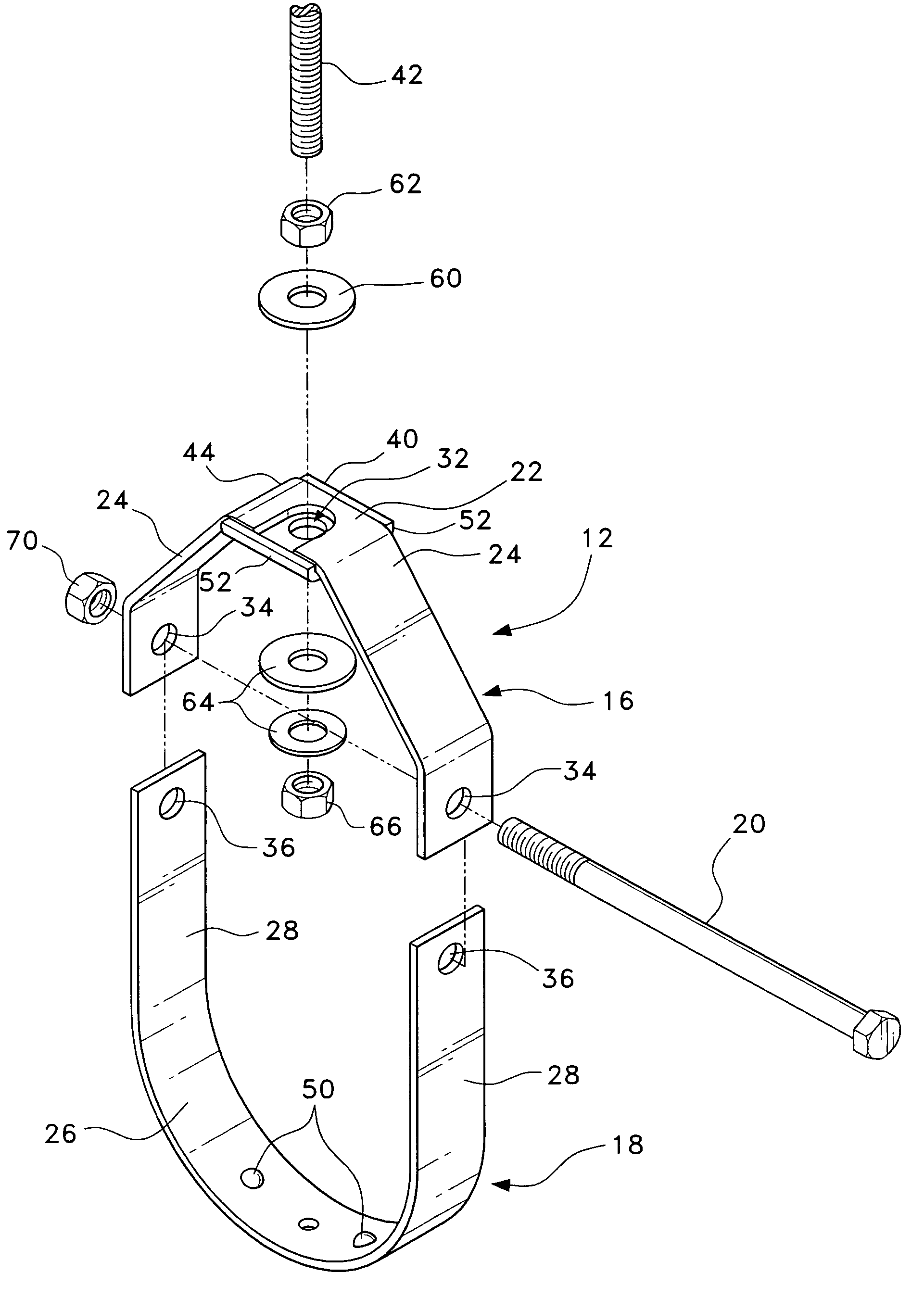
[0016]The present invention is a pipe hanger assembly, designated generally as 10 in the drawings. The pipe hanger assembly 10 generally comprises a pipe hanger and a holding assembly for attachment to a pipe support.

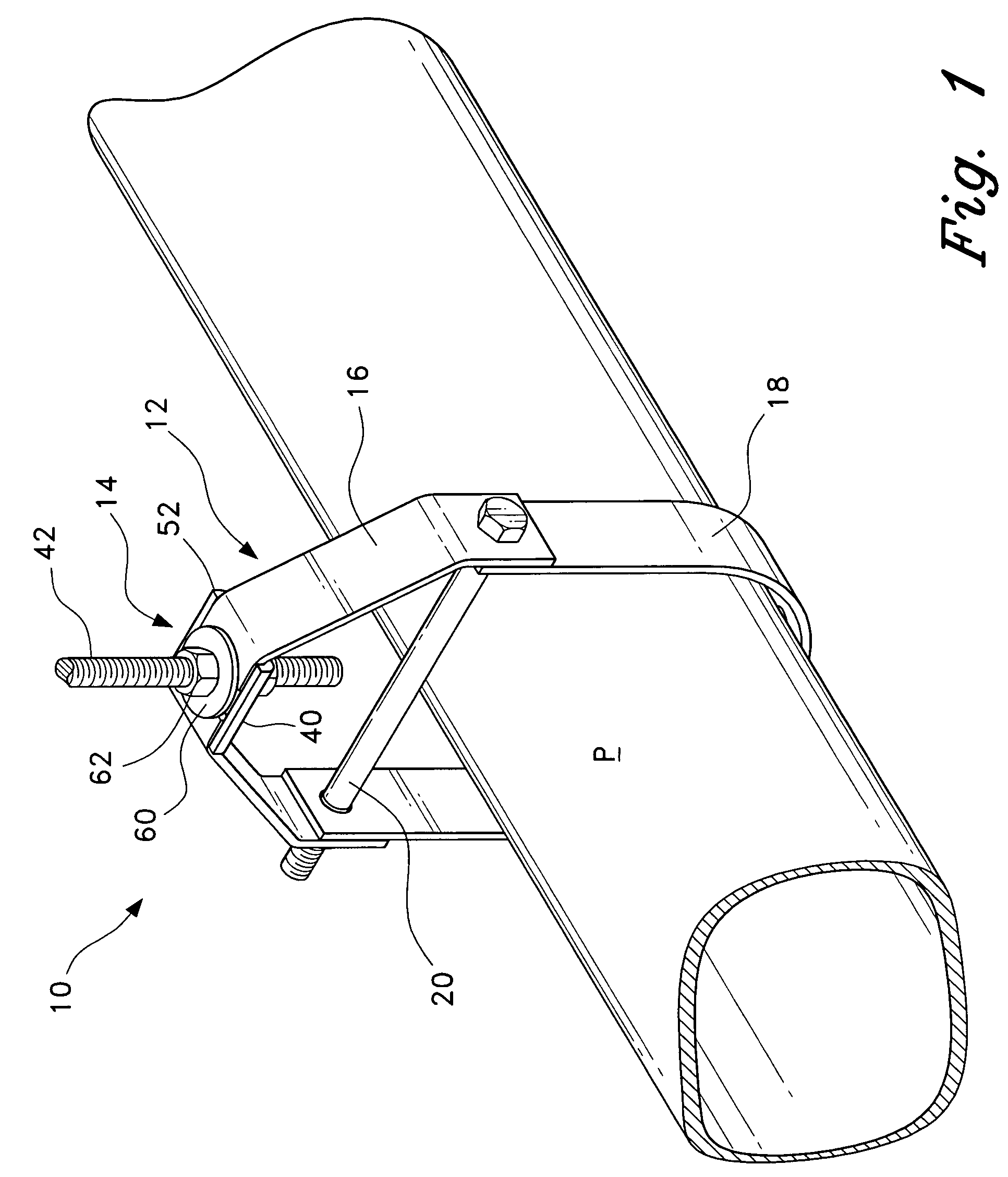
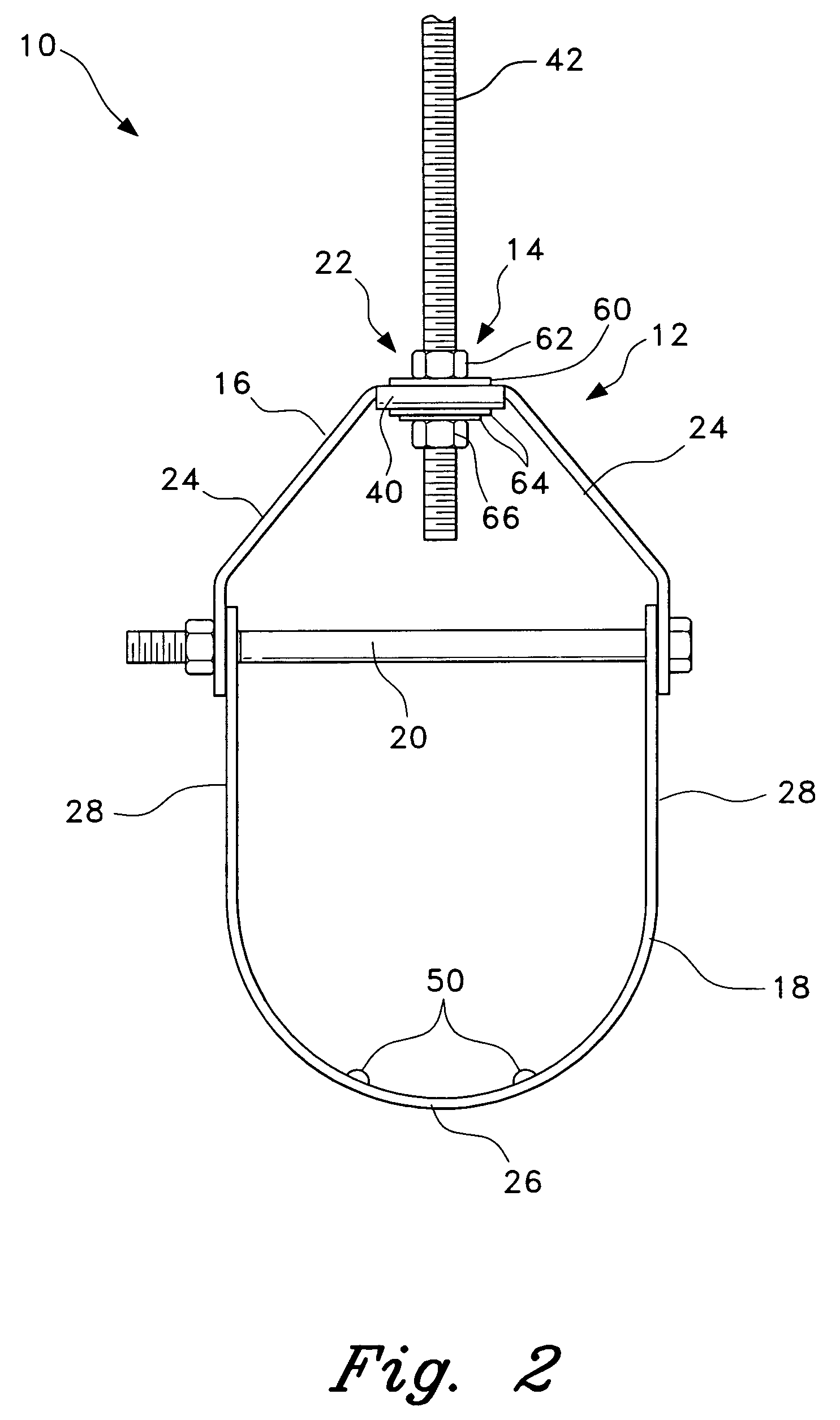
[0017]Referring first to FIG. 1, an environmental, perspective view of the pipe hanger assembly 10 is shown with a pipe P suspended from the pipe hanger assembly 10. The pipe hanger assembly 10 comprises a pipe hanger 12 and a holding assembly 14. The pipe hanger 12 has an inverted, generally U-shaped upper yoke 16 having a slot 32 defined in the bight of the yoke 16 (seen more clearly in FIG. 3), a generally U-shaped saddle 18, and a bolt 20 connecting the yoke 16 and saddle 18 to each other. The holding assembly 14 includes at least a bracket 40. The holding assembly 14 may also include a threaded rod 42, a plurality of washers 60 and 64 and a plurality of nuts 62 and 66. The bracket 40 is a plate having a pair of opposing flanges 52 defining a channel having a width ...


PUM


Abstract

The pipe hanger assembly is a pipe hanger and a holding assembly for retaining the pipe hanger against a pipe support. The pipe hanger has an inverted, generally U-shaped yoke having a slot defined in the bight of the yoke, a U-shaped saddle for supporting the pipe, and a bolt connecting the yoke and the saddle to each other. The holding assembly is at least a bracket having a pair of flanges defining a guide channel, the bracket being attached to a stud, threaded rod, or other pipe support suspended from a ceiling. The pipe hanger is assembled to the pipe, the bracket is attached to the rod, and the yoke is slid onto the rod between the bracket and a keeper, the yoke being aligned with the guide channel. The keeper is tightened to secure the pipe hanger to the pipe support. A pair of embossments protrude from an inner surface of the saddle.

Description

BACKGROUND OF THE INVENTION[0001]1. Field of the Invention[0002]The present invention relates to fixtures for supporting pipe and conduit, and particularly to a clevis pipe hanger assembly.[0003]2. Description of the Related Art[0004]Pipe hangers, and specifically clevis pipe hangers, are often used for suspending piping from ceilings. The hangers typically comprise an upper hanger or yoke that is attached with a U-shaped lower hanger that supports the pipe. There is an elongated bolt extending through aligned apertures in the arms of the yoke and the U-shaped lower hanger. During installation, the clevis hanger is slid onto the pipe while the pipe is on the ground. Then, the installer lifts the pipe with the hanger and slides the clevis hanger into position for the support process. The installer secures the pipe and hanger by tightening a nut on the bottom of the bolt.[0005]A problem arises when the installer is trying to raise the pipe and secure the lower hanger to the yoke. Gene...

Claims


Application Information

Patent Timeline
Patent Type & Authority Patents(United States)
IPC IPC(8): E21F17/02F16L3/00
CPCF16L3/11F16L3/133F16L3/18Y10T403/581Y10T403/4628Y10T403/1683F16B2200/406F16B2200/69
Inventor CONNOLLY, MICHAEL J.
Owner CONNOLLY MICHAEL J
Why Eureka
Try Eureka