Piezoelectric transducer assembly

a technology of piezoelectric transducers and components, applied in the direction of generators/motors, instruments, liquid/fluent solid measurements, etc., can solve problems such as sensor instability and error

Inactive Publication Date: 2007-10-30
ONICON INC
View PDF7 Cites 11 Cited by
  • Summary
  • Abstract
  • Description
  • Claims
  • Application Information

AI Technical Summary

Benefits of technology

[0008]Resonant piezoelectric transducer assemblies are commonly used in time-of-flight acoustic flow measurement instruments for transmitting and receiving acoustic signals through a fluid isolated from the transducer assembly by a window. In a preferred embodiment of the invention, such a transducer assembly comprises a thickness-mode piezoelectric ceramic body, a pair of foil conductors with mesh end portions, and a coupling medium used to fill in the interstices in the meshes. In this embodiment, the ceramic body may be a disk or tile and is arranged for thickness-mode operation having electrode layers on two parallel facing surfaces. The foil conductors are held in contact with the electrode layers, either by an adhesive bond, a mechanical clamping force, or combination thereof. One of the conductors is placed between one face of the ceramic body and the window, while the other is held between the other face of the ceramic body and a backing body, which may be an acoustic isolator (e.g., a polymeric foam). Among other alternatives, the backing body may also be a resonant isolating structure comprising a resonant body having a thickness corresponding to a quarter of the wavelength at which the transducer operates and an acoustic mass that is selected to be substantially heavier than the ceramic element. The structure may additionally comprise isolating sheets of material, which may be polymeric, that are positioned on either side of the resonator so that one of them is between the resonator and the backing body and the other is between the resonator and the surface with the foil conductor.

Problems solved by technology

The acoustic coupling of these elements to the fluid, which is complicated by the need to attach electrical connections to the acoustically active transducer surfaces, is generally the major source of sensor instability and error.

Method used


Image

  • Piezoelectric transducer assembly
  • Piezoelectric transducer assembly
  • Piezoelectric transducer assembly

Examples


Embodiment Construction

[0014]In studying this Detailed Description, the reader may be aided by noting definitions of certain words and phrases used throughout this patent document. Wherever those definitions are provided, those of ordinary skill in the art should understand that in many, if not most instances, such definitions apply to both preceding and following uses of such defined words and phrases. At the outset of this Description, one may note that the terms “include” and “comprise,” as well as derivatives thereof, mean inclusion without limitation; the term “or,” is inclusive, meaning and / or.

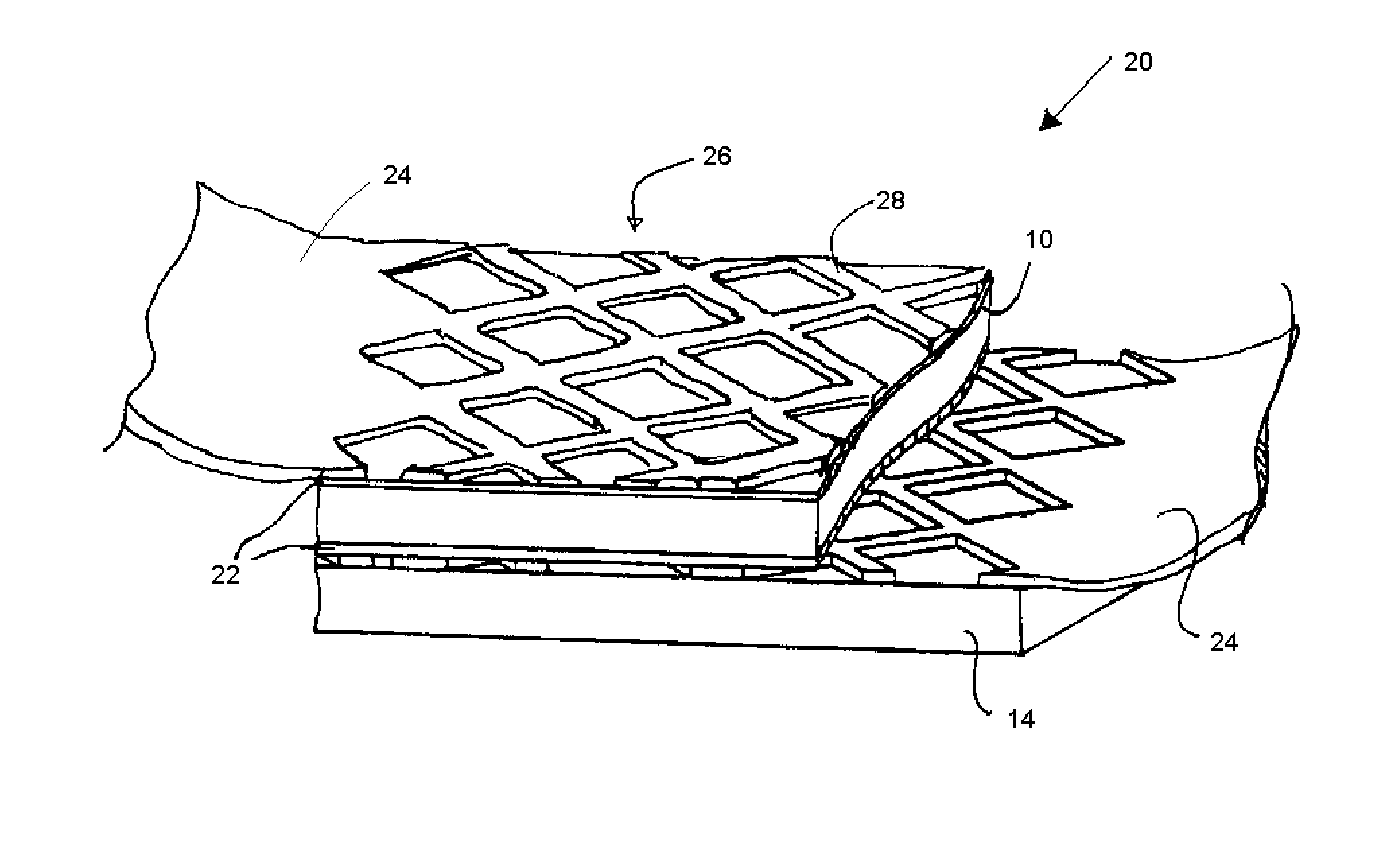
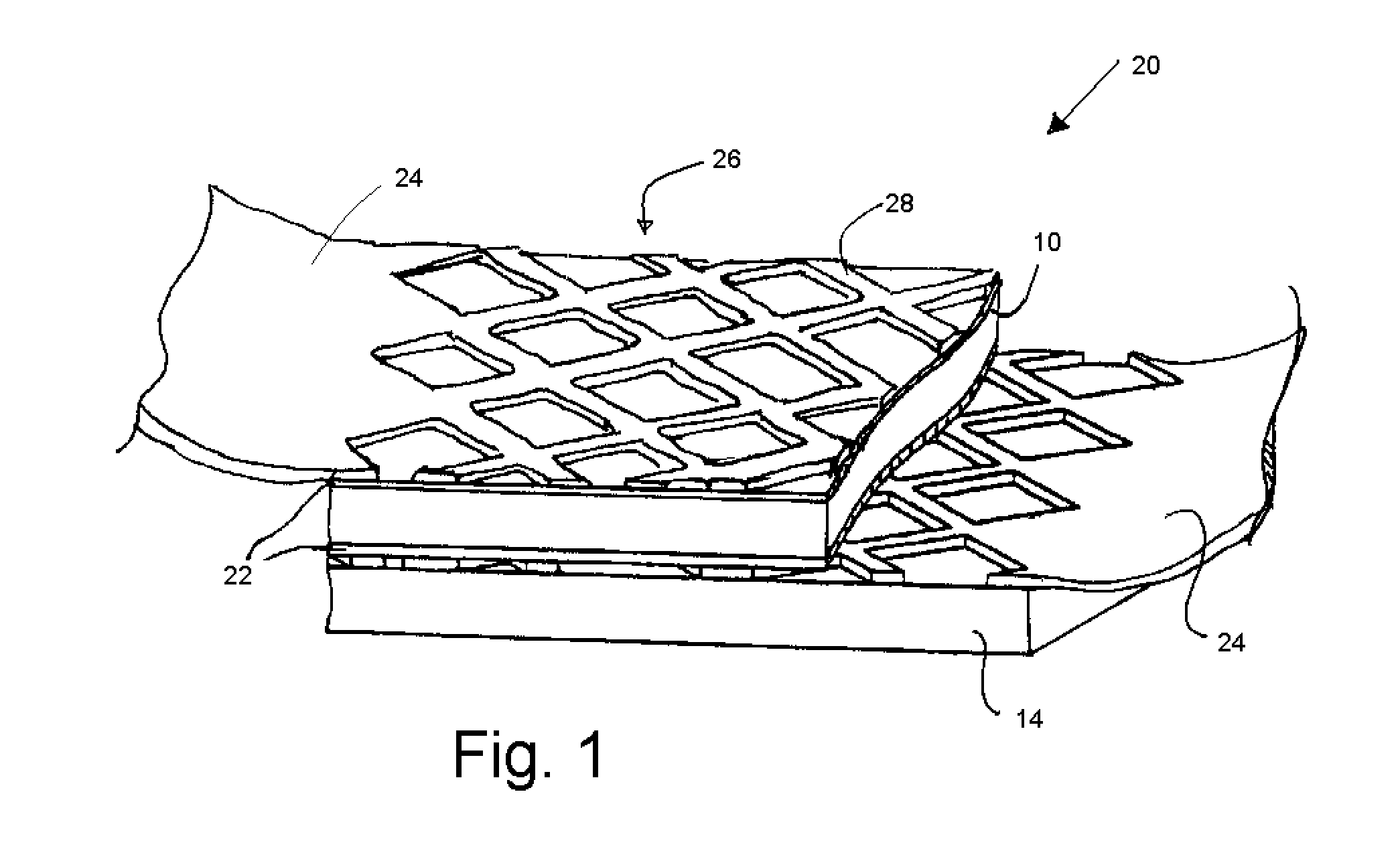
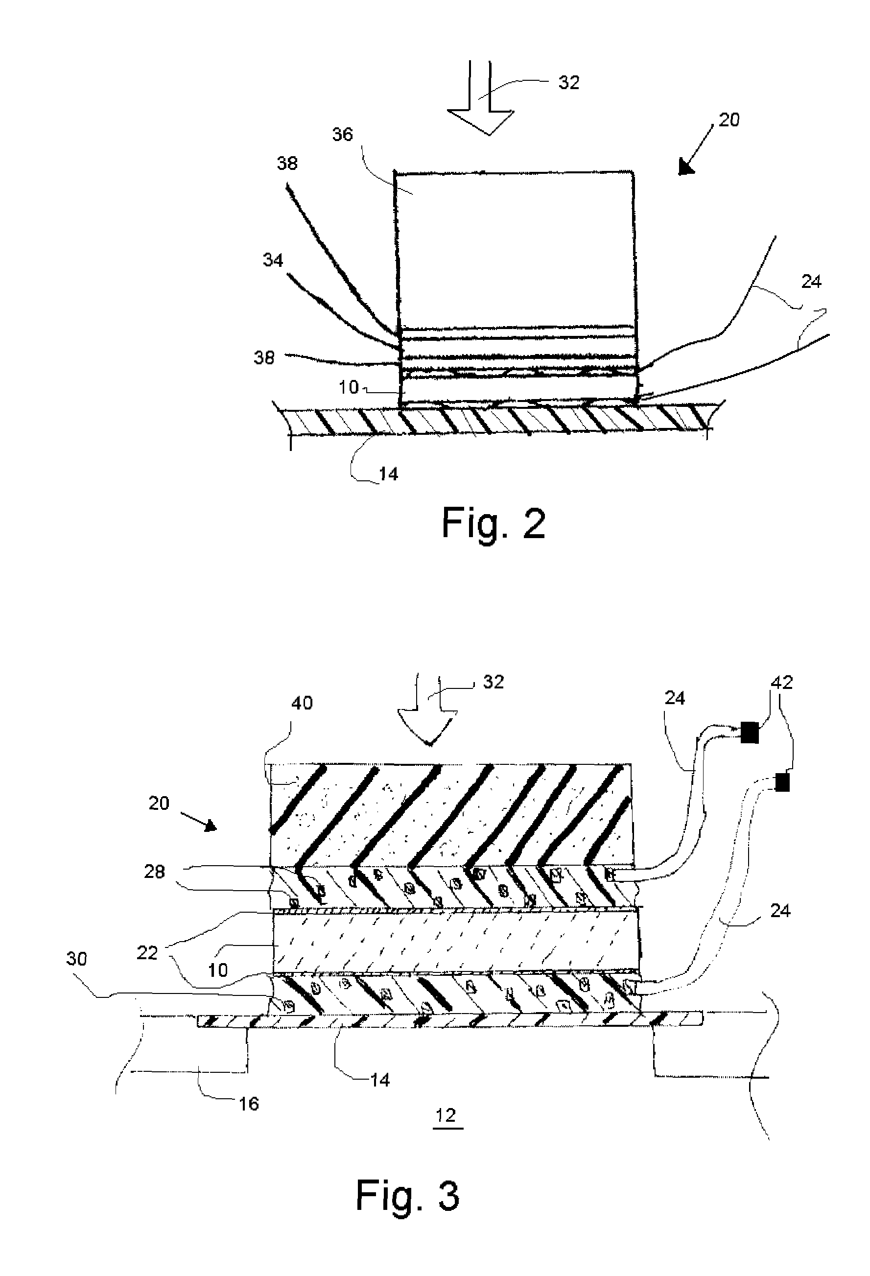
[0015]In acoustic flow measurement equipment it is conventional to separate various electrical components, such as the piezoelectric ceramics 10, from the working fluid 12, as depicted in FIG. 3. The element of the measurement system that performs this function is an acoustically transparent window 14 that may be integrally formed with a wall of the system (e.g., may be a portion of a pipe) or that may be a se...


PUM


Abstract

A transducer assembly may comprise a thickness-mode piezoelectric ceramic body, a pair of foil conductors with mesh end portions, and a coupling medium used to fill in the interstices in the meshes. The foil conductors are held in contact with the electrode layers by a selected combination of adhesive mechanical clamping forces. One of the conductors is placed between one face of the ceramic body and a window that separates the transducer assembly from a fluid to be measured. The other conductor is held between the other face of the ceramic body and a backing body, which may be an acoustic isolator or a resonant isolating structure comprising a resonant body and an acoustic mass that is substantially heavier than the ceramic element. The structure may additionally comprise isolating sheets of material, which may be polymeric, that are positioned on either side of the resonator so that one of them is between the resonator and the backing body and the other is between the resonator and the surface with the foil conductor.

Description

BACKGROUND OF THE INVENTION[0001]1. Field of the Invention[0002]This invention relates to piezoelectric transducers and particularly to those transducers in apparatus for determining the rate of flow of a fluid in which the propagation times of ultrasonic signals transmitted through the fluid are detected to determine flow rate.[0003]2. Background Information[0004]Ultrasonic transit time flow sensors, also known as “time of flight ultrasonic flow sensors”, detect the acoustic propagation time difference between ultrasonic signals transmitted upstream and downstream through a flowing fluid and process the time difference information to derive the fluid flow rate. The propagation time difference is usually very small and must be detected with high resolution and stability for the sensor to be practical. These sensors typically use piezoelectric transducer elements to generate and detect the acoustic signals. The acoustic coupling of these elements to the fluid, which is complicated by...

Claims


Application Information

Patent Timeline
Patent Type & Authority Patents(United States)
IPC IPC(8): H01L41/08
CPCG10K11/002G01F1/662
Inventor FELLER, MURRAY F
Owner ONICON INC
Why Eureka
Try Eureka