Image forming apparatus with selectively rotated developing roller

a development roller and development roller technology, applied in the direction of electrographic process apparatus, instruments, optics, etc., can solve the problems of excessive wear of toner and the layer thickness restricting member, wasteful consumption of toner inside the apparatus, and inability to reduce the effect of reducing the holding current and preventing darkness

Inactive Publication Date: 2007-11-06
SEIKO EPSON CORP
View PDF18 Cites 4 Cited by
  • Summary
  • Abstract
  • Description
  • Claims
  • Application Information

AI Technical Summary

Benefits of technology

[0016]The invention resolves the above-described problems and reduces useless consumption of toner, contamination in the image forming apparatus and wear and deterioration of the toner and a layer thickness restricting member or the like in continuously forming an image.
[0017]The invention also reduces a variation in rotation and a non-uniformity in rotation of the photosensitive body by restraining a rapid variation of a load of the photosensitive body accompanied by acceleration and deceleration of a developing roller.

Problems solved by technology

Therefore, even when development is not actually carried out, for example, the developing roller is opposed to an interval between the latent images of the photosensitive body, so-to-speak an interval between sheets, the developing roller continues rotating while carrying the toner and therefore, the toner is wastefully consumed to contaminate inside of the apparatus.
Therefore, while the developing roller is rotating, the developing roller and the layer thickness restricting member and the toner, or the toners are slid to produce friction and are considerably worn.
Therefore, when the developing roller continues to rotate during a time period of from printing on a first sheet to finishing printing on a final sheet, particularly including a time period during which development is not carried out as in the case of printing continuously a plurality of sheets of images by a single color toner, there poses a problem that there is a concern that the toner and the layer thickness restricting member are uselessly worn, proper electric charge is not applied to the toner, and image quality of the formed image is deteriorated.
Further, since almost all of printing only by the single color toner is carried out by a toner in black color and therefore, there poses a problem that wear of the single color toner and wear of the member of the developing device is more progressed than that of toners of other colors and amounts of wearing members constituting the developing device significantly differ from each other among the developing device.
Therefore, there poses a problem that a variation in the speed of the processing member rotating in steady state is increased and so-to-speak non-uniformity in rotation is brought about.
Therefore, there poses the problem that the variation in the speed of the photosensitive body is increased and so-to-speak non-uniformity in rotation is brought about.
Even in the case in which the latent image formed on the photosensitive body is not being developed, when the latent image is being formed on the photosensitive body or when the toner image formed on the photosensitive body is being transferred, the non-uniformity in rotation of the photosensitive body constitutes a non-uniformity in the latent image or a non-uniformity in the transferred toner image and as a result, there poses a problem that image quality is deteriorated by bringing about a non-uniformity in the image.

Method used


Image

  • Image forming apparatus with selectively rotated developing roller
  • Image forming apparatus with selectively rotated developing roller
  • Image forming apparatus with selectively rotated developing roller

Examples


Embodiment Construction

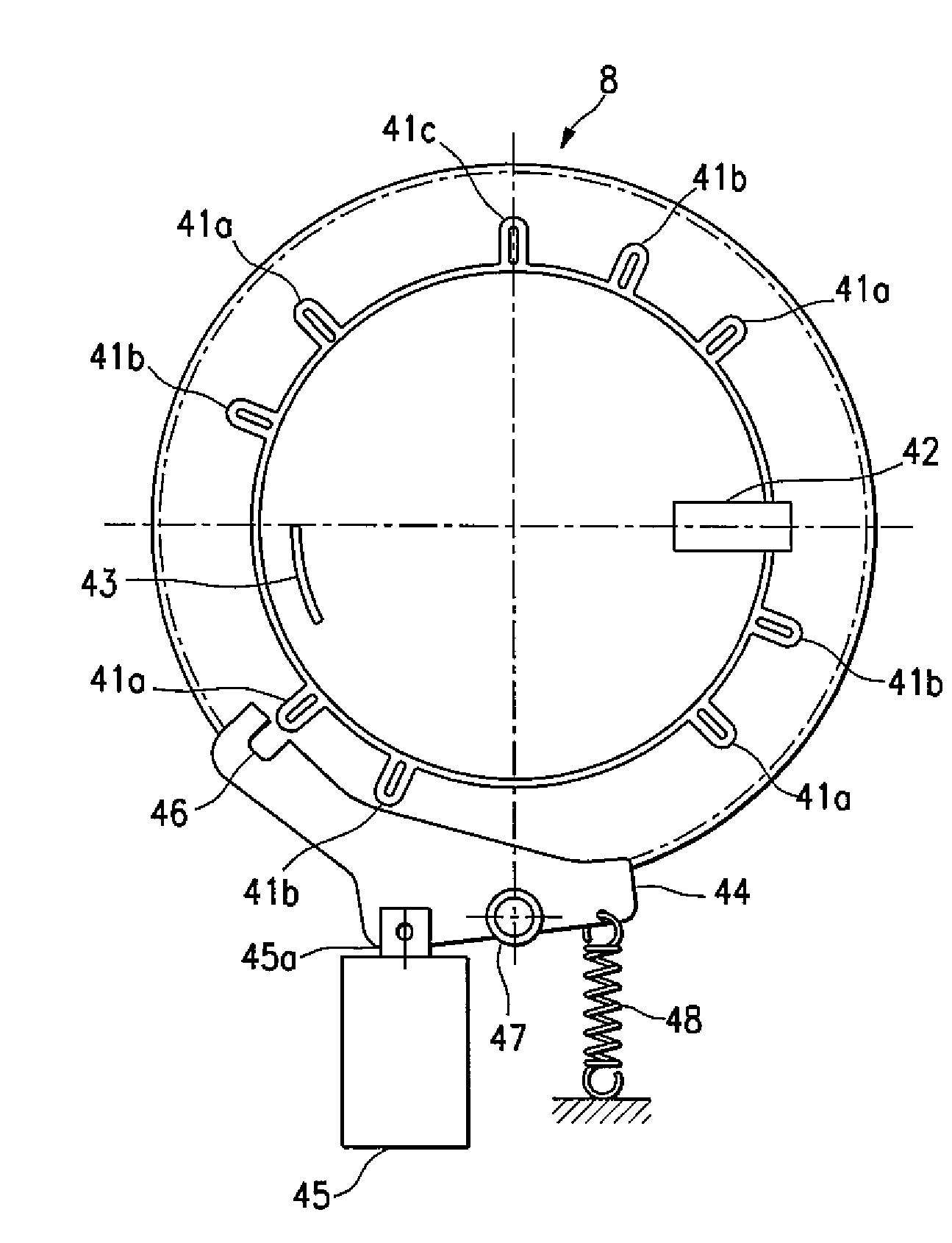
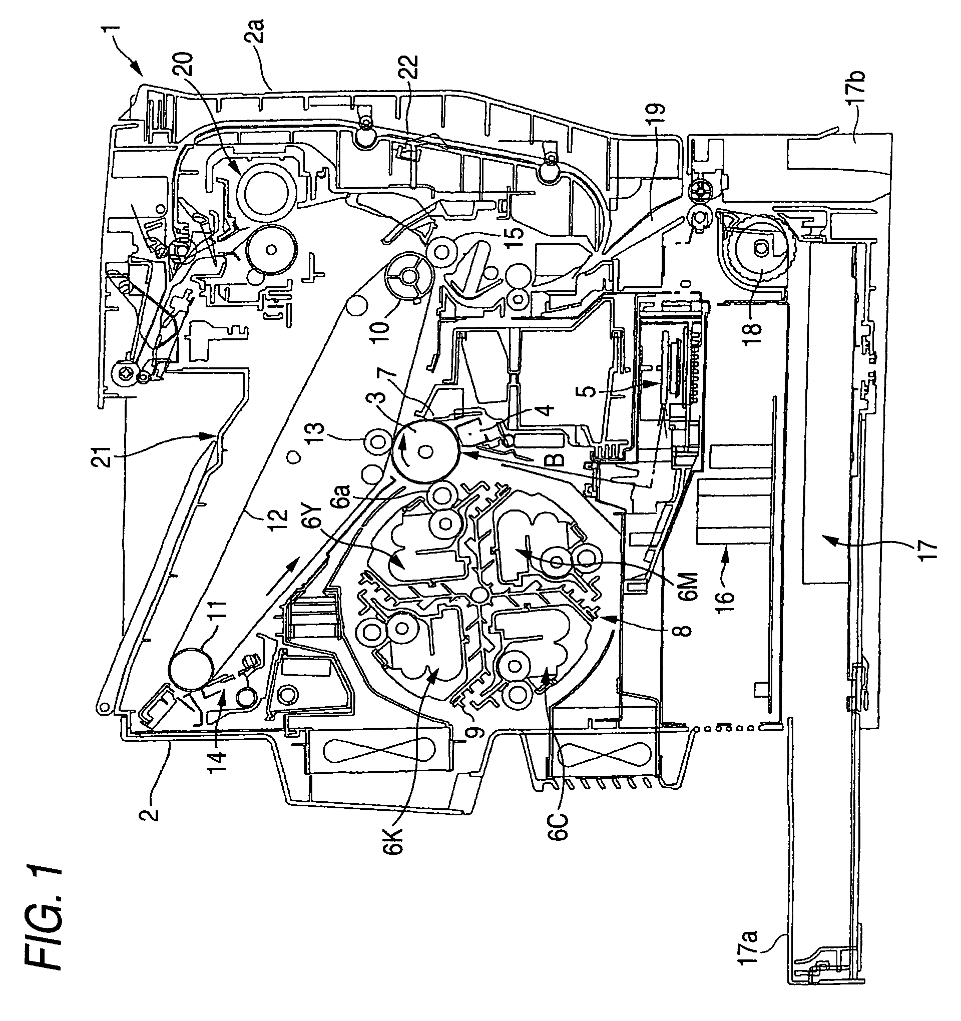
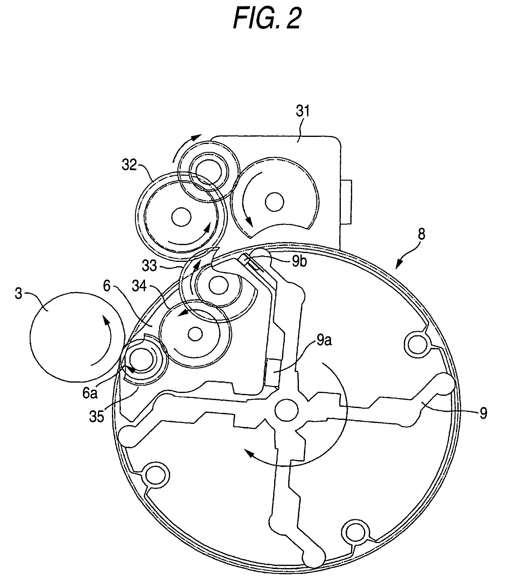
[0045]An explanation will be given of an embodiment of the invention in reference to the drawings as follows. FIG. 1 is a view showing an embodiment of an image forming apparatus, in the drawing, numeral 1 designates an image forming apparatus, numeral 2 designates a main body case, numeral 3 designates a photosensitive body, numeral 4 designates a charging device, numeral 5 designates an exposing device, numeral 6 designates a developing device, numeral 7 designates a photosensitive body cleaner, numeral 8 designates a rotary development apparatus, numeral 9 designates a rotary frame, numeral 12 designates an intermediate transferring belt, numeral 13 designates a primary transferring roller, numeral 14 designates a transferring belt cleaner, numeral 15 designates a secondary transferring roller, numeral 16 designates a power source apparatus, numeral 17 designates a charge tray, numeral 20 designates a fixing unit, numeral 21 designates a discharge tray, and numeral 22 designates ...


PUM


Abstract

An image forming apparatus includes an image carrier formed with a latent image A developing device has a developing roller driven by a stepping motor. A rotary development apparatus supports the developing device on a rotating shaft to rotate to a developing position opposed to the image carrier to form an image by developing the latent image formed at the image carrier and transfers the developed image to a medium at a transferring position The developing roller is driven by the stepping motor in a region of the latent image of the image carrier and is stopped in a holding state in a region in which the latent image is not formed by a current lower than a current in driving the developing roller.

Description

[0001]The present application is based on Japanese Patent Applications Nos. 2003-295009 and 2003-302422, the entire contents of which are incorporated herein by reference.BACKGROUND OF THE INVENTION[0002]1. Field of the Invention[0003]The present invention relates to an image forming apparatus to form an image by developing a latent image formed on an image carrier by a development apparatus and transferring the developed developer image at a transferred position.[0004]More specifically the present invention relates to an image forming apparatus having the image carrier formed with the latent image, a developing device having a developing roller driven to rotate by a stepping motor and carrying a developer for developing the latent image, and a rotary development apparatus for supporting the developing device centering on a rotating shaft to move to rotate to a developing position opposed to the image carrier and constituted to form the image by developing the latent image formed at...

Claims


Application Information

Patent Timeline
Patent Type & Authority Patents(United States)
IPC IPC(8): G03G15/08G03G15/01
CPCG03G15/0121G03G15/0818G03G15/0813G03G2215/0177
Inventor MIYAZAWA, HIROSHIKISHIGAMI, MINORUTANAKA, KUNIAKIMIZUSHIMA, NOBUYUKI
Owner SEIKO EPSON CORP
Why Eureka
Try Eureka