
Filtration system with enhanced cleaning and dynamic fluid separation

a filtration system and fluid separation technology, applied in the field of fluid separation, can solve the problems of high construction cost, labor-intensive, inefficient intermittent stopping of a filtration process, and the need to manually or chemically clean upstream surfaces of filter media, and achieve the effect of reducing the number of filtration operations

Inactive Publication Date: 2007-11-13
PHASE
View PDF152 Cites 23 Cited by
  • Summary
  • Abstract
  • Description
  • Claims
  • Application Information

AI Technical Summary

Benefits of technology

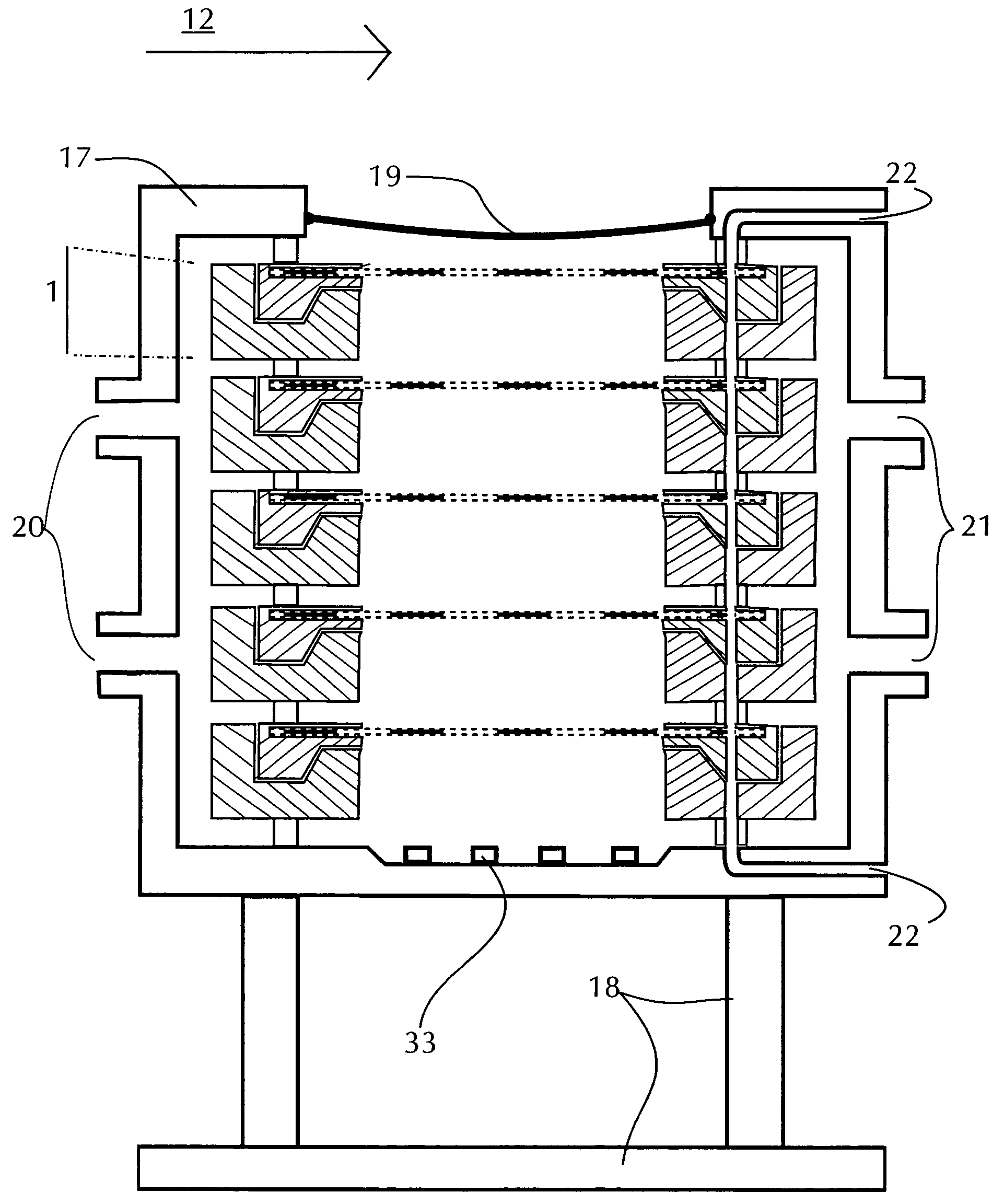
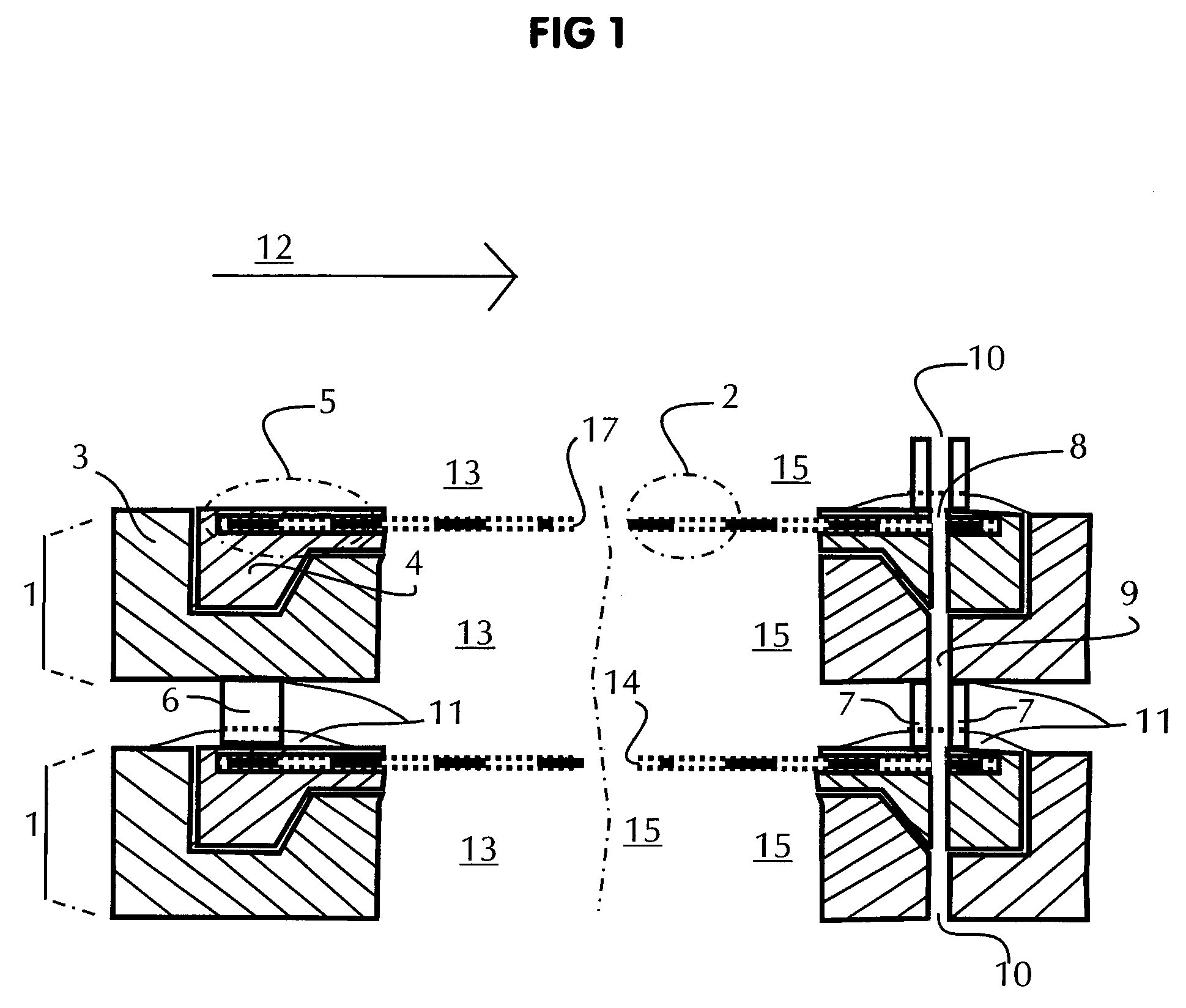
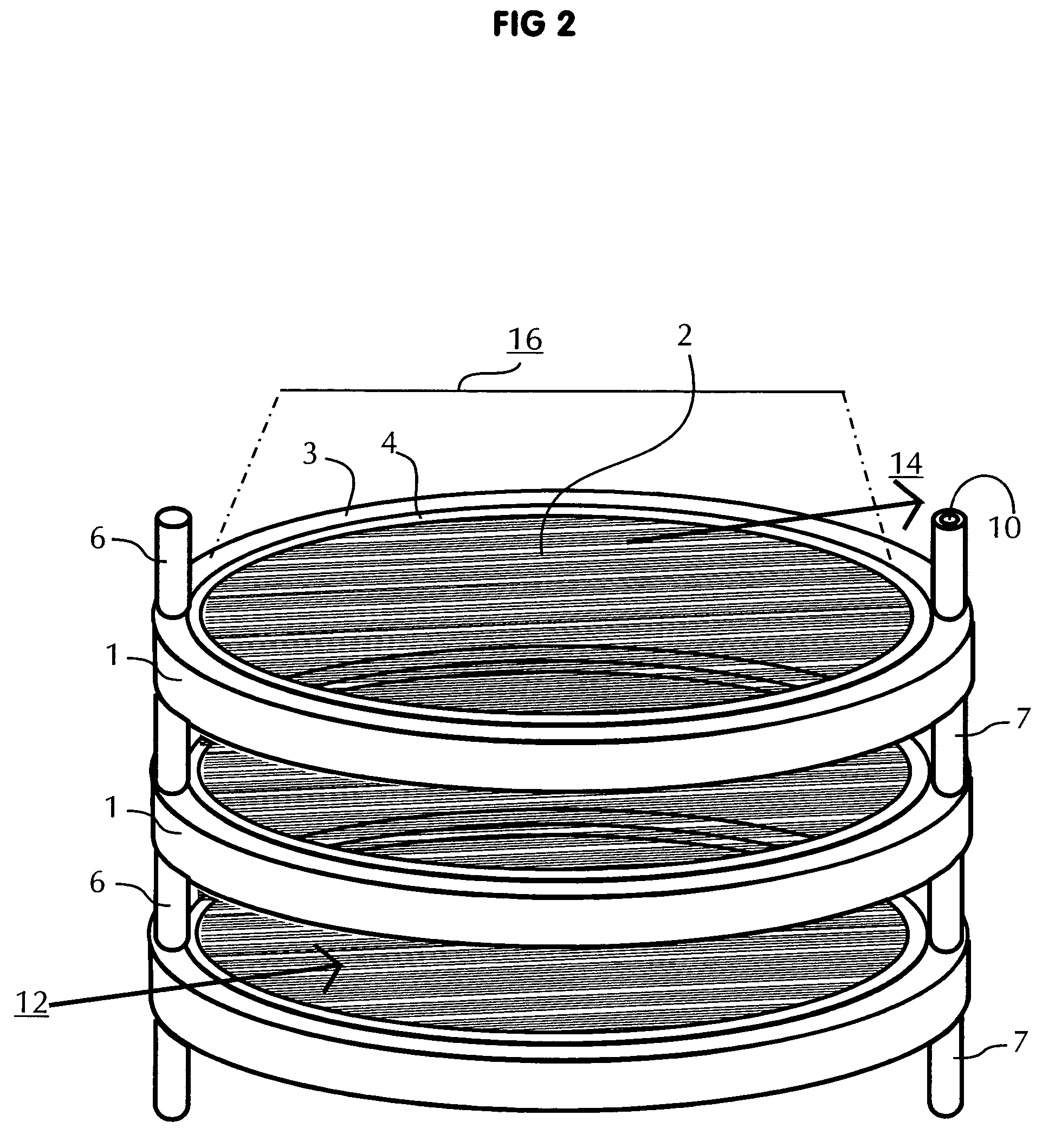
[0015]In accordance with teachings of the present invention a filtration system may be provided with at least one membrane sheet or other types of filter media tensioned along two or more edges, or along its entire periphery edge with a relatively open work space to accommodate cleaning of the filter media without stopping an associated filtration process. Tensioning filter media in accordance with teachings of the present invention allows membranes or other types of filter media to flex or bounce like a trampoline, or alternatively, stretch, so as to induce twisting, torsional or other surface changes, all enabling use of various techniques for cleaning membrane surfaces or other types of filter media while an associated filter system remains in full operation.
[0016]Another aspect of the present invention includes providing filter systems and filter elements satisfactory for cleaning to remove scale, solids cake and / or film layers without interrupting or stopping an associated filtration process. For example, filter elements may be formed with a central, open work area which is not blocked or obstructed by base plate stiffening members or mechanical spacing elements. As a result, the present invention allows direct vibration or alternatively acoustic and / or sonic waves to directly contact associated membranes or other types of filter media for cleaning.

Problems solved by technology

Intermittently stopping a filtration process to manually or chemically clean upstream surfaces of filter media or to backwash clarified fluid through associated filter media is generally inefficient, labor-intensive, and expensive.
Relatively high construction costs may be required to build structures that can withstand these constant reciprocating motions and high amounts of energy often required to generate such motion to provide commercially viable amounts of upstream membrane cleaning, for applications of sufficient value to justify the costs.

Method used


Image

  • Filtration system with enhanced cleaning and dynamic fluid separation
  • Filtration system with enhanced cleaning and dynamic fluid separation
  • Filtration system with enhanced cleaning and dynamic fluid separation

Examples


Embodiment Construction

[0054]Various embodiments of the invention and its advantages are best understood by reference to FIGS. 1–33 wherein like numbers refer to same and like parts.

[0055]Dynamic filtration may be defined as the use of membranes or other filter media capable of substantially continuous operation with either no interruption of an associated filtration process or substantially reduced frequency of cleaning that interrupts an otherwise substantially continuous filtration process.

[0056]Process fluid may generally be defined as a fluid stream containing liquids and / or gases along with suspended solids, colloidal and / or particulate matter. Fluid permeable membranes and other types of filter media may be used to separate various components of a process fluid in accordance with teachings of the present invention.

[0057]Membranes and other types of filter media may have an upstream side, which is the side or face communicating with a process fluid. Membranes and other types of filter media generall...


PUM

PropertyMeasurementUnit
energyaaaaaaaaaa
energy absorbingaaaaaaaaaa
vibration energyaaaaaaaaaa

Abstract

A filtration system is provided with filter media operable to remove solids, particulate and colloidal matter from a process fluid. Acoustic, vibration and sonic energy may be used to clean associated filter media to allow substantially continuous filtration of process fluids. The filtration system may be satisfactorily used with process fluids having a relatively high concentrations of solids, particulate and colloidal matter.

Description

CROSS REFERENCE TO RELATED APPLICATIONS[0001]This application claims priority to U.S. Provisional Patent Application Ser. No. 60 / 491,581, filed Jul. 30, 2003, and entitled “Tensioned Leaf Filter Elements With Perpendicular Vibration.”[0002]This application also claims priority to U.S. Provisional Patent Application Ser. No. 60 / 491,579, filed Jul. 30, 2003, and entitled “Tensioned Stack Plate Filter With Perpendicular Vibration.”[0003]This application also claims priority to U.S. Provisional Patent Application Ser. No. 60 / 491,572, filed July 30, 2003, and entitled “Tensioned Leaf Filter Element With Perpendicular Vibration And Harmonics Control.”[0004]This application also claims priority to U.S. Provisional Patent Application Ser. No. 60 / 491,571, filed Jul. 30, 2003, and entitled “Tensioned Stack Plate Filter With Perpendicular Vibration And Harmonics Control.”[0005]This application also claims priority to U.S. Provisional Application Ser. No. 60 / 566,199, filed Apr. 27, 2004, and en...

Claims


Application Information

Patent Timeline
Patent Type & Authority Patents(United States)
IPC IPC(8): B01D65/00B01D61/00B01D63/00C02F1/44B01DB01D65/02
CPCB01D63/08B01D63/082B01D63/10B01D63/16B01D65/02B01D65/08B01D2321/2075B01D2313/20B01D2313/36B01D2321/00B01D2321/185B01D2321/2058
Inventor KIRKER, CURTISFULLER, BERKELEY F.
Owner PHASE
Learn More