Image forming apparatus

a technology of forming apparatus and forming blade, which is applied in the direction of electrographic process apparatus, instruments, optics, etc., can solve the problems of brush not being able to satisfactorily remove the throwaway toner image, the cleaning apparatus designed to electrostatically remove toner cannot reduce the amount of toner particles, and the cleaning blade tends to frictionally wear the recording medium bearing member or intermediary transfer belt. , to achieve the effect of short tim

Active Publication Date: 2011-01-25
CANON KK
View PDF11 Cites 7 Cited by
  • Summary
  • Abstract
  • Description
  • Claims
  • Application Information

AI Technical Summary

Benefits of technology

[0010]Thus, the primary object of the present invention is to provide an image forming apparatus capable of satisfactorily cleaning its recording medium bearing member or intermediary transfer member in a short length of time, with the use of its cleaning member designed to electrostatically remove toner, during an operation in which a throwaway toner image is formed.

Problems solved by technology

However, even with the recording medium bearing member or intermediary transfer member charged to the same polarity as the normally charged toner, it is impossible to prevent the problem that some of the toner particles making up the throwaway toner image still transfer from the image bearing member onto the recording medium bearing member or intermediary transfer member.
However, a cleaning blade tends to frictionally wear the recording medium bearing member or intermediary transfer belt.
However, the brush failed to satisfactorily remove the throwaway toner image.
That is, the toner particles on the recording medium bearing member or intermediary transfer belt, which were insufficient in the amount of electrical charge, fail to be electrostatically removed, remaining therefore on the surface of the recording medium bearing member or intermediary transfer belt.
However, a cleaning apparatus designed to electrostatically remove toner cannot reduce the amount by which toner particles which are small in the amount of electrical charge remain adhered to the recording medium bearing member or intermediary transfer member.

Method used


Image

  • Image forming apparatus
  • Image forming apparatus
  • Image forming apparatus

Examples


embodiment 1

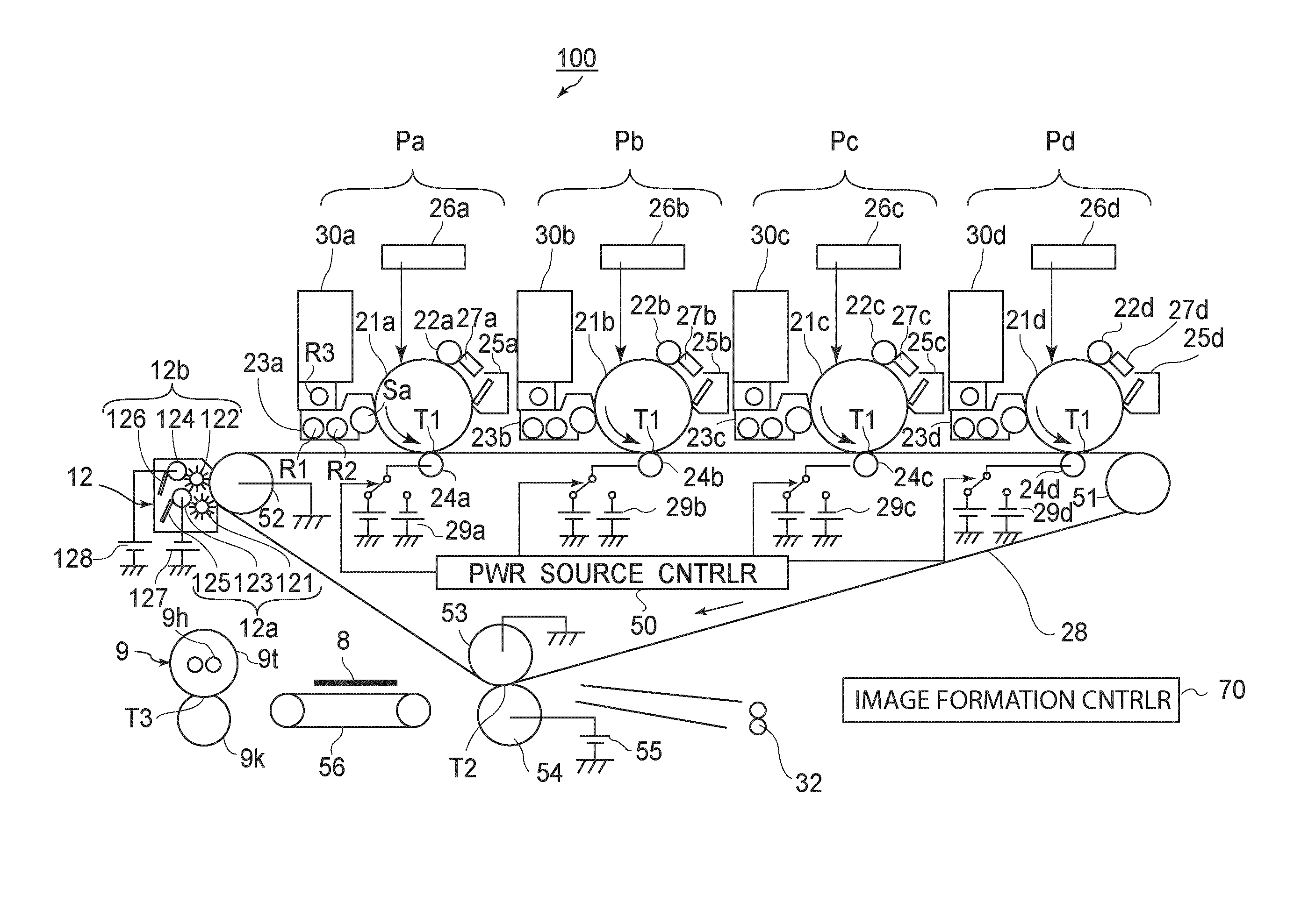
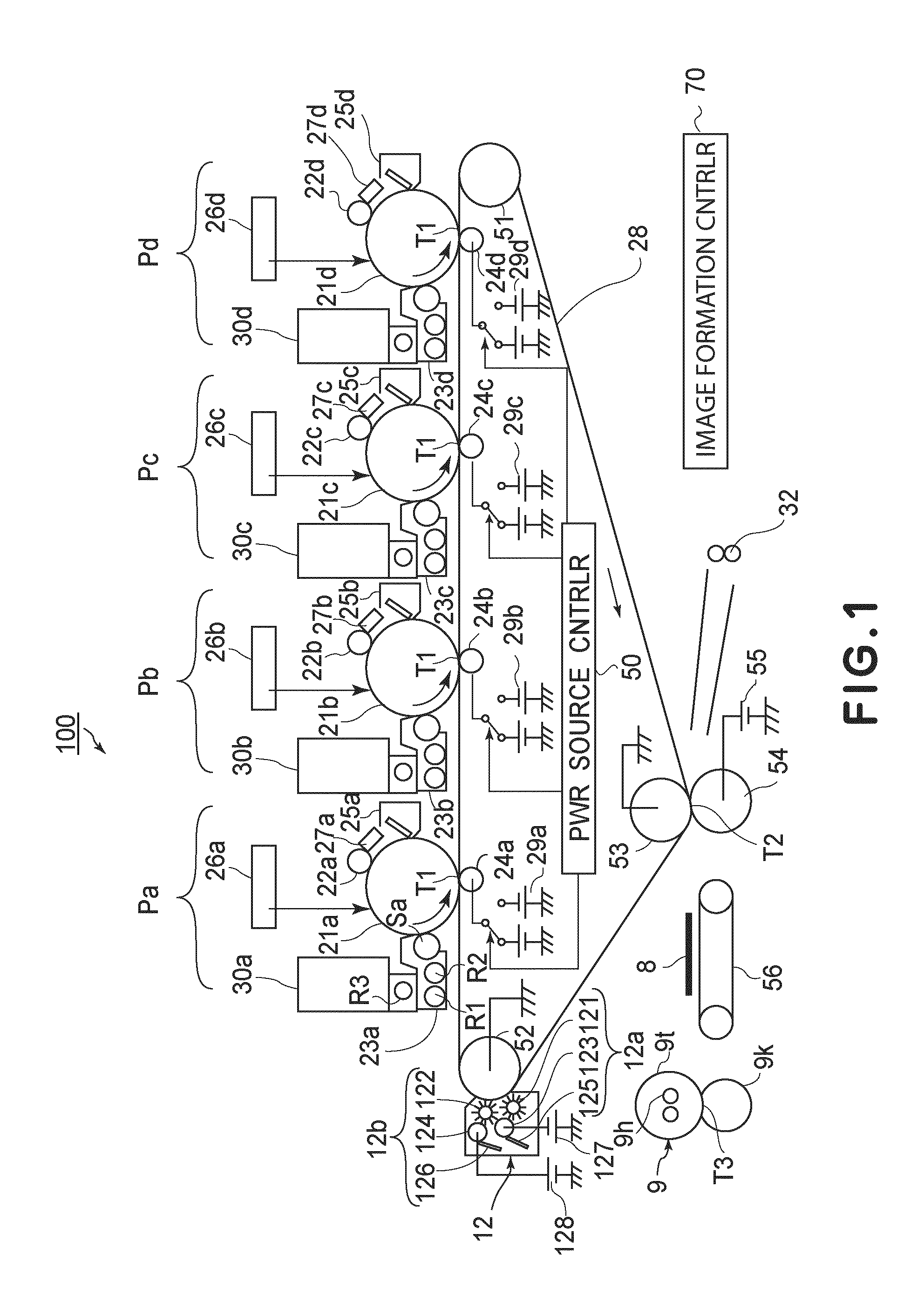
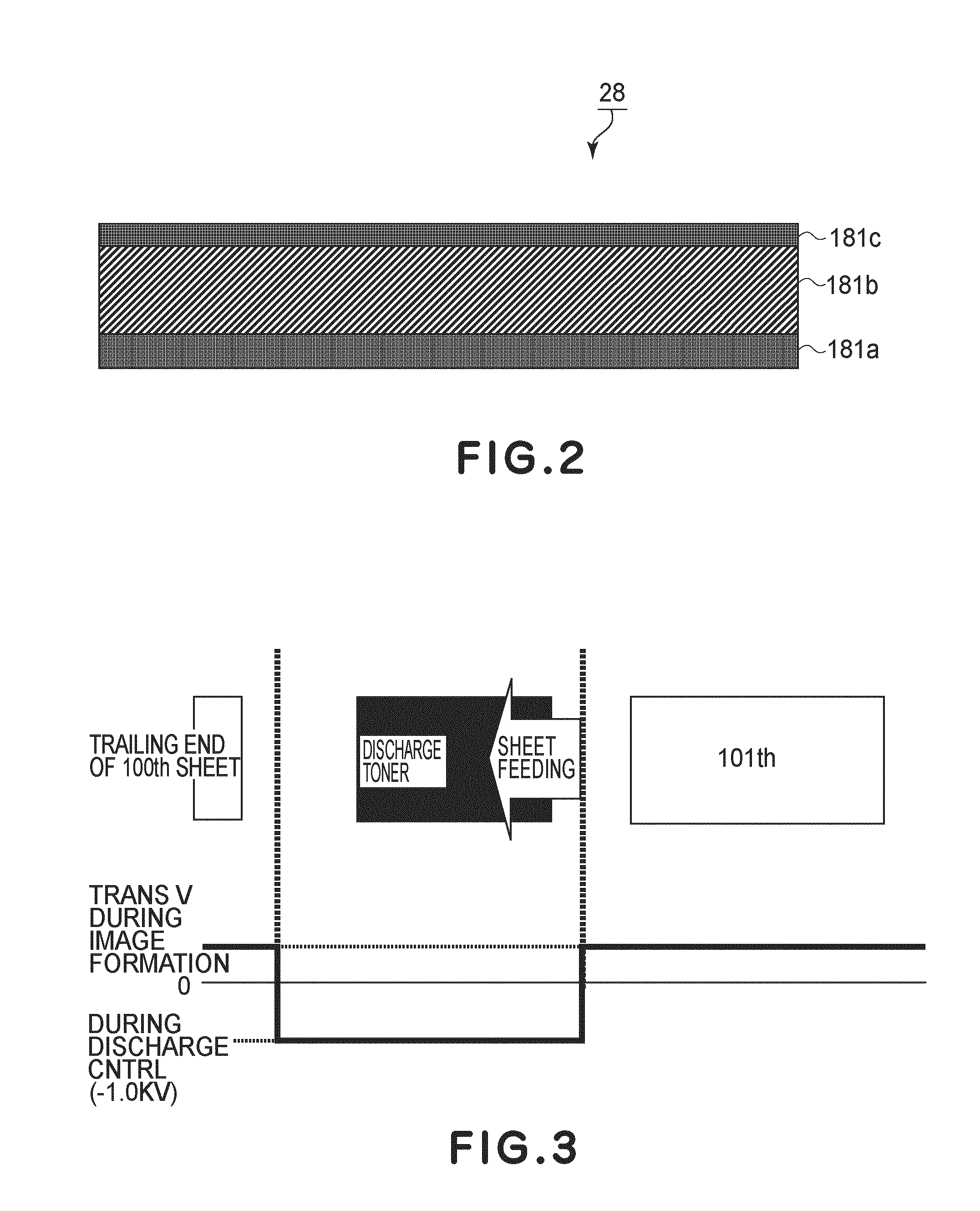
[0028]FIG. 1 is a schematic sectional view of the image forming apparatus in the first embodiment of the present invention, and shows the structure of the apparatus. FIG. 2 is a schematic sectional view of the intermediary transfer belt, and shows the structure of the belt. The image forming apparatus 100 in the first embodiment is a full-color image forming apparatus of the so-called tandem type, which has yellow, magenta, cyan, and black image forming portions Pa, Pb, Pc, and Pd (toner image forming means), which are juxtaposed in the adjacencies of the outward side of the top portion of the loop which the intermediary transfer belt 28 forms.

[0029]Referring to FIG. 1, the intermediary transfer belt 28, which is an example of an intermediary transfer member, is stretched around a driver roller 51, a follower roller 52, and a secondary transfer roller 53, being thereby suspended by the three rollers. The driver roller 51 is rotationally driven by an unshown motor (for example, stepp...

embodiment 2

[0101]FIG. 10 is a schematic sectional view of the image forming apparatus in the second embodiment of the present invention, and shows the structure of the apparatus. The image forming apparatus 200 in the second embodiment is the same in structure as the image forming apparatus 100 in the first embodiment, except that the image forming apparatus 200 is provided with a recording medium conveying belt 38 instead of the intermediary transfer belt 28. That is, the image forming portions Pa, Pb, Pc, and Pd, cleaning apparatus 12, fixing apparatus 9, etc., of the image forming apparatus 200 are the same as those of the image forming apparatus 100. Thus, the structural components of the image forming apparatus 200, which are shown in FIG. 10, and correspond to those of the image forming apparatus 100, which are shown in FIG. 1, are given the same referential symbols as those given to the corresponding components of the image forming apparatus 100, in order not to repeat the same descript...


PUM


Abstract

An image forming apparatus includes an image bearing member, a toner image forming member, an intermediary transfer member for forming a primary transfer portion, and a primary transfer member supplied with a transfer voltage. The apparatus also has a voltage source for supplying, to the primary transfer member, a transfer voltage and a voltage of a polarity opposite to the transfer voltage, an image bearing member cleaning apparatus for removing toner from the image bearing member, a secondary transferring member, and an intermediary transfer member cleaning apparatus for electrostatically removing toner from the intermediary transfer member. The apparatus further has a voltage source control apparatus for controlling the voltage source so as to apply, to the primary transfer member, a voltage having an absolute value larger than a discharge threshold and having the polarity opposite to the transfer voltage, when a non-recording toner pattern passes through the primary transfer portion.

Description

FIELD OF THE INVENTION AND RELATED ART[0001]The present invention relates to an image forming apparatus in which a toner image formed on its image bearing member is transferred (primary transfer) onto its intermediary transfer member, is moved through the primary transfer area by the movement of the intermediary transfer member while voltage which is the same in polarity as the normally charged toner is applied to the primary transfer member, and is removed by its cleaning apparatus for cleaning the image bearing member. More specifically, it relates to the control of the voltage which is applied to the primary transfer member while the toner image is moved through the primary transfer area, and which is the same in polarity as the normally charged toner.[0002]The present invention relates to an image forming apparatus in which a toner image formed on its image bearing member is transferred (primary transfer) onto a recording medium borne on its recording medium conveying member, an...

Claims


Application Information

Patent Timeline
Patent Type & Authority Patents(United States)
IPC IPC(8): G03G15/16
CPCG03G15/1605G03G2215/0129G03G2215/0161G03G2215/1614G03G15/161
Inventor TAKEUCHI, YASUSHI
Owner CANON KK
Why Eureka
Try Eureka