Apparatus for controlling deceleration of hydraulically powered equipment

a technology for hydraulically powered equipment and apparatus, which is applied in the direction of electric controllers, couplings, fluid couplings, etc., can solve the problems of increasing the time required, oscillating the swing of the boom assembly, and increasing the time required

Active Publication Date: 2007-11-20
HUSCO INT INC
View PDF12 Cites 34 Cited by
  • Summary
  • Abstract
  • Description
  • Claims
  • Application Information

AI Technical Summary

Problems solved by technology

As a result, the boom assembly swing oscillates until inherent dampening provided by other forces ultimately brings the assembly to a stop.
This phenomenon is known as “bounce” or “wag” and increases the time required to properly position the boom 6, thereby adversely affecting equipment productivity.
The wag also is disconcerting to the machine operator.
In other words, the valve closes when motion of the boom is to terminate, however the load force acting on the boom does not allow the velocity of the boom to decrease fast enough.

Method used


Image

  • Apparatus for controlling deceleration of hydraulically powered equipment
  • Apparatus for controlling deceleration of hydraulically powered equipment
  • Apparatus for controlling deceleration of hydraulically powered equipment

Examples


Embodiment Construction

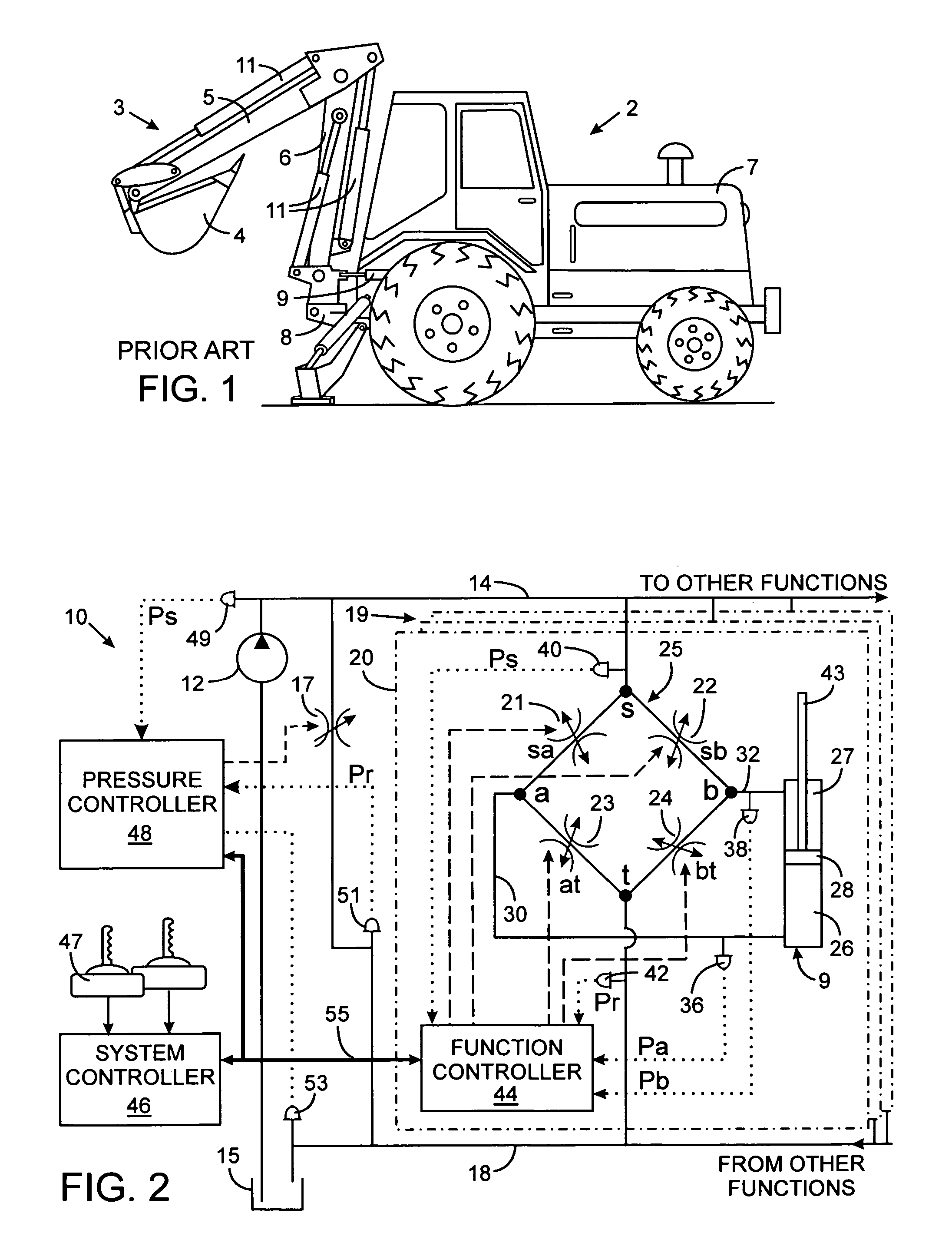
[0022]Although the present invention is being described in the context of use on a backhoe as shown in FIG. 1, it has application on other types of machines in which large inertia machine functions are attached to the hydraulic actuator and exhibit controllability difficulties.

[0023]With initial reference to FIG. 2, the elements of the boom assembly 3 of the backhoe 2 are moved by a novel hydraulic system 10 that includes the hydraulic actuators, such as the boom swing cylinder 9. The hydraulic system 10 has a positive displacement pump 12 that is driven by a motor or engine (not shown) to draw fluid from a tank 15 and furnish the fluid under pressure to a supply conduit 14. An unloader valve 17 (such as a proportional pressure relief valve) is connected between the supply conduit 14 and a tank return conduit 18 that leads to the system tank 15. Operation of the unloader valve 17 regulates pressure in the supply conduit 14. The novel technique for reducing wag described herein also ...


PUM


Abstract

A machine member driven by a hydraulic actuator may oscillate, or wag, when the hydraulic actuator decelerates or stops. The degree of oscillation is a function of the machine member's ability to track a deceleration command, which ability varies with changes in the position of the machine member and the load force acting thereon. To reduce the oscillation, a command that controls operation of the hydraulic actuator is filtered using a filter function that changes with the machine member's load. The load force exerted on the hydraulic actuator which in turn can be designated by fluid pressure that results from the hydraulic actuator. Preferably, the frequency of the filter function is varied inversely with the magnitude of the actuator load force.

Description

CROSS-REFERENCE TO RELATED APPLICATIONS[0001]Not ApplicableSTATEMENT REGARDING FEDERALLY SPONSORED RESEARCH OR DEVELOPMENT[0002]Not ApplicableBACKGROUND OF THE INVENTION[0003]1. Field of the Invention[0004]The present invention relates to hydraulically powered equipment, such as off-road construction and agricultural vehicles, and more particularly to apparatus for reducing oscillation or wag when a hydraulically driven member on the equipment is decelerating, stopping, or reversing direction.[0005]2. Description of the Related Art[0006]With reference to FIG. 1, a backhoe 2 is a common type of earth moving equipment that has a boom assembly 3 comprising a bucket 4 attached to the end of an arm 5 which in turn is coupled by a boom 6 to the frame of a tractor 7. Three hydraulic cylinders 11 form actuators that are operated independently to move the bucket, arm, and boom. A pivot joint 8 allows the boom assembly 3 to swing left and right with respect to the rear end of the tractor 7. A...

Claims


Application Information

Patent Timeline
Patent Type & Authority Patents(United States)
IPC IPC(8): F16D31/02
CPCE02F9/2207E02F9/22G05B11/01
Inventor PFAFF, JOSEPH L.
Owner HUSCO INT INC
Why Eureka
Try Eureka