Structure of display rack

a technology for display racks and structures, applied in the field of display racks, can solve the problems of cumbersome stocking and material management operations, difficult transportation and storage, and disadvantages of many types of beams to meet different configuration requirements

Inactive Publication Date: 2007-11-20
HUNG MING CHUN +1
View PDF8 Cites 35 Cited by
  • Summary
  • Abstract
  • Description
  • Claims
  • Application Information

AI Technical Summary

Benefits of technology

[0013]From the description of the mechanical structure and associated operational characteristics, the present innovative design provides flexibility in the number of and space between main beams as well as means of adding support beams and face-plates. This invention has the additional advantage of adding extension sockets at the end of each main beam, so the structure can be repeated to fill the required space and display need.

Problems solved by technology

First, traditionally these supporting beams are welded together. Although welding makes a strong connection, the bulky structure makes them difficult to transport and store.
Secondly, to meet different configuration and strength requirements, many types and sizes of beams are needed resulting in cumbersome stocking and material management operation.
Thirdly, to avoid the problems created by welding connection, some manufacturers also provide screws and bolts type of connections which use ball-shaped connectors to put together extension beams. This type of structure has the advantage of easy assembly but at the expense of labor extensive and time consuming operations in the field. Again, it has the disadvantage of stocking many types of beams to meet different configuration requirements.
Fourthly, on top of these, the prior arts use screws and press-fit gadgets to fasten face-plates for marking and description of goods displayed onto the displaying racks. These steps are also labor extensive and time consuming.

Method used


Image

  • Structure of display rack
  • Structure of display rack
  • Structure of display rack

Examples


Embodiment Construction

[0029]The following descriptions are of exemplary embodiments only, and are not intended to limit the scope, applicability or configuration of the invention in any way. Rather, the following description provides a convenient illustration for implementing exemplary embodiments of the invention. Various changes to the described embodiments may be made in the function and arrangement of the elements described without departing from the scope of the invention as set forth in the appended claims.

[0030]In the following, detailed description along with the accompanied drawings explains fully the preferred embodiments of the present invention.

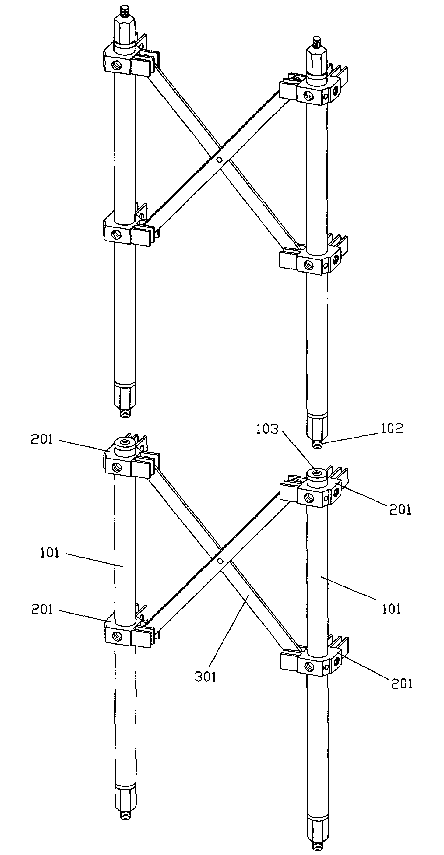
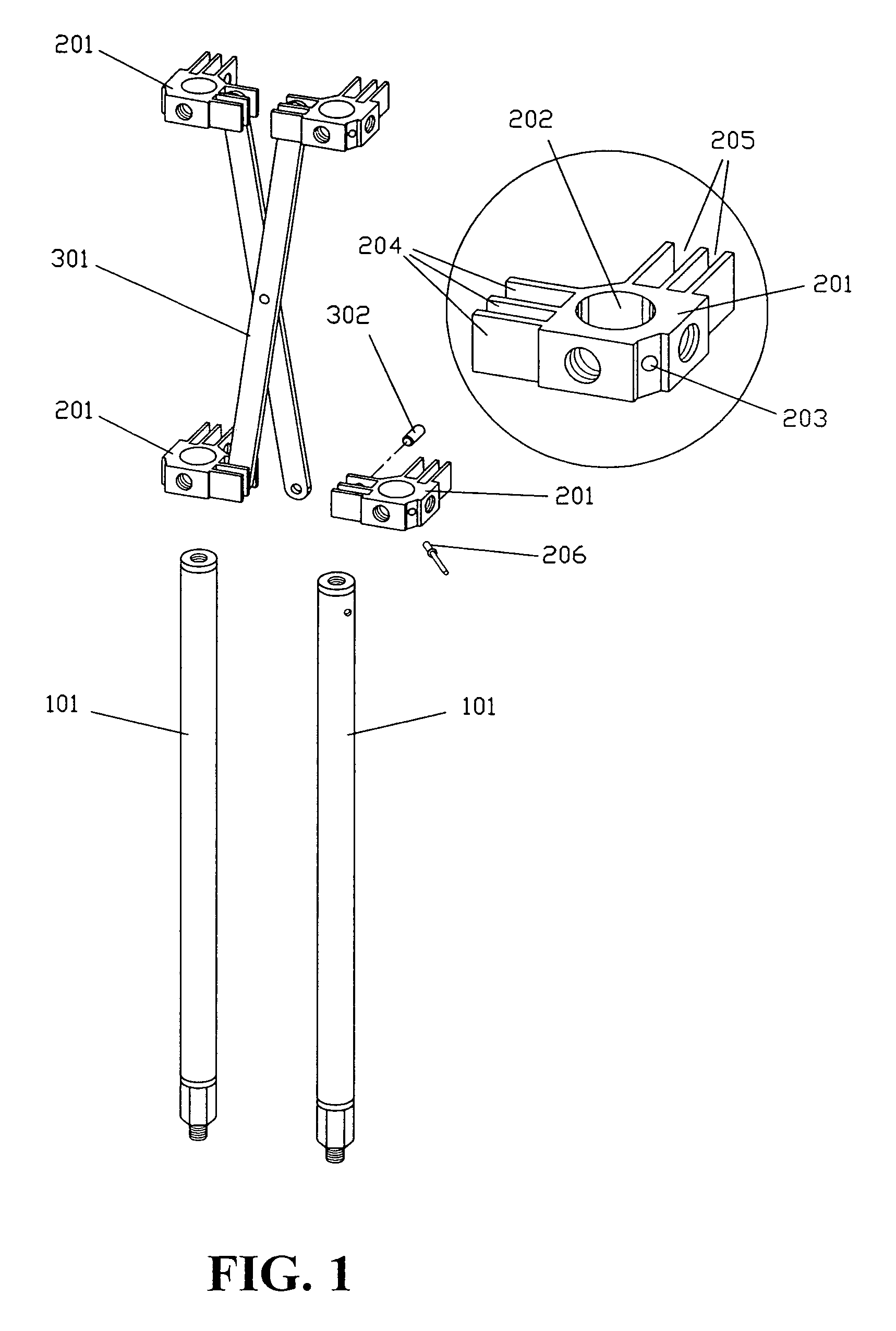
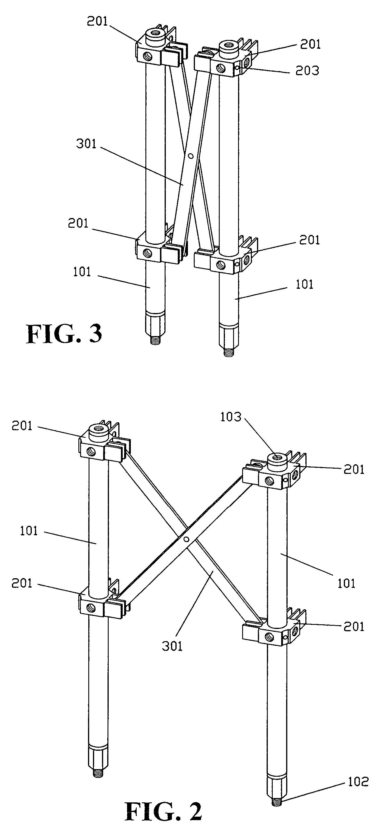
[0031]As shown in FIG. 1, this invention is a beam structure for assembled display rack. The embodiment of the present invention comprises main beams 101, connecting sockets 201, and diagonal support beams 301. The embodiment will take at least two main beams which are shallow cylinder with pre-defined length, several connecting sockets, and a number o...


PUM


Abstract

A structure of a display rack which includes a plurality of main beams, connecting sockets, diagonal support beams, and extension sockets, characterized in that the main beam is of pre-defined length, the connecting socket is movable along the main beam, the diagonal support beam is installed in slots formed by the fins of the connecting sockets, and the slots are used for the attachment of face plates.

Description

BACKGROUND OF THE INVENTION[0001](a) Technical Field of the Invention[0002]The present invention generally relates to display racks that are to be assembled on the field, and more particularly to a flexible, highly efficient, and easy to assemble display rack structure used in show room or exhibition hall.[0003](b) Description of the Prior Art[0004]Many businesses in their show rooms and / or exhibition halls use temporary structures such as display racks and / or frames for their mobility and functionality. These structures are designed for easy assembly to achieve flexibility and convenience in transportation and storage.[0005]Most of these designs use a few basic types of beams that can be put together easily. To obtain the necessary strength of the finished structure, the construction is usually consisted of two or more main beams connected with several connecting or supporting beams in between. The disadvantages of prior arts are:[0006]First, traditionally these supporting beams ar...

Claims


Application Information

Patent Timeline
Patent Type & Authority Patents(United States)
IPC IPC(8): A47B43/00
CPCA47B47/005A47B47/028A47F5/14A47F5/10A47B87/02
Inventor HUNG, MING-CHUNHUNG, HAO-YUN
Owner HUNG MING CHUN
Why Eureka
Try Eureka